
Abstract
Well-aligned zinc oxide (ZnO) nanorods are fabricated on indium-tin-oxide (ITO) coated glass substrates via self-assembly of ZnO nanoparticles created using continuous spray pyrolysis (CoSP) technique. The method involves pre-treatment by dip-coating the substrate with a solution comprising of zinc salt for creating a seed layer, and then spray-pyrolyzed ZnO nanoparticles self-assemble on the pre-treated substrate. The effect of the substrate pre-treatment and the deposition time (tdep) of nanoparticles is investigated. The results show that the substrate pre-treatment influences the growth of ZnO nanorods which are absent without the pre-treatment. Nanoparticle collection and nanorod growth on different substrates are done simultaneously. The thin films of as-grown nanorods are used as photoelectrode materials to fabricate dye-sensitized solar cells (DSSCs) and the effect of nanorods grown for different times has been studied. The best performance with this cell structure is found for the layer with tdep=15 min, which showed a conversion efficiency of 1.77% for the cell area of 0.25 cm2.
Export citation and abstract BibTeX RIS

Content from this work may be used under the terms of the Creative Commons Attribution-NonCommercial-ShareAlike 3.0 licence. Any further distribution of this work must maintain attribution to the author(s) and the title of the work, journal citation and DOI.
1. Introduction
Zinc oxide (ZnO) is a wide band gap, n-type semiconductor and has emerged as a material of interest for a variety of electronic applications, such as solar cells [1], UV photonics [2], transparent high-power electronics, varistors [3], surface acoustic wave devices, piezoelectric transducers [4] and gas sensing devices [5]. The performance of these devices depends critically on the morphology, size and dimension, which in turn determine the electrical and thermal transport properties in addition to the optical and mechanical properties of ZnO material. Due to having a total of 13 fastest growth directions and a pair of {0001} polar-surfaces [6–8] wurtzite structured ZnO has been demonstrated to form a diverse group of morphologies such as nanowires [9,10], nanorods [11,12], nanonails [13], nanobridges [13], nanoprisms [14], nanotubes [15], nanobelts [7], nanorings [16,17], nanowhiskers [18,19], nanocombs [20], nanohelices [21,22], nanosprings [21], nanopropellers [23], nanobows [24], nanocages [25], nanodisks [26,27], nanopoints [28], nanopores [29] and tetrapods [30]. Among those nanostructures, vertically well-aligned ZnO nanorod arrays, which have a large surface-to-volume ratio, have been extensively studied and demonstrated using a variety of techniques. It is desirable to develop fast and simple routes for the synthesis of high-quality ZnO nanostructures in large quantity to explore the diverse applications of this material.
Dye-sensitized solar cell (DSSC) utilizes an oxide photoelectrode (TiO 2, ZnO, etc.) having nanopores for efficient dye adsorption and electron injection [31]. There are various reports in the literature which have exhibited the use of ZnO nanostructures as photo-electrode material in DSSC fabrications [32]. Rangarao et al showed that ZnO-based DSSC has an efficiency of ∼2.8% for nanoparticle film and 4.7% for nanorod morphology (in the plane of the substrate) film [33]. The increase in the efficiency is due to increase in the amount of dye adsorption for the film having nanorod morphology.
The range of reported efficiencies for vertical ZnO-nanorod-based DSSCs fabricated using different methods is very wide and their values are still low [34–37]. For hydrothermally grown nanorods (using different conditions), the reported efficiencies are 0.84% for 5.5 μm [35], 1.0% for 11 μm [37] and 1.5% for 20 μm long rods. On the other hand, for vapor deposited rods (5–6 μm length) the efficiency is 0.34% [34]. Recently, Lai et al reported 1.82% conversion efficiency for DSSC fabricated with ZnO nanorods on sapphire substrates by chemical vapor deposition method [38]. Sudhagar et al explored highly branched ZnO nanorods as a photoelectrode in dye-sensitized solar cells and compared with that of branch-free ZnO nanorods. They showed that the jacks like ZnO nanorods DSSCs render a conversion efficiency of 1.82% higher than that of branch free ones (η=1.08%) [39]. Yoshikawa et al have shown an increase in the cell performance with increase in the nanorod length for solution grown layer [40]. They report an increase in the conversion efficiency from 0.94 to 1.69% for increasing nanorod lengths from 2.6 to 10.8 μm. It has also been shown that photovoltaic response of ZnO nanorods is dependent not only on the rod size but also on their orientation [41,42].
In this work, morphological changes of ZnO films grown in a continuous spray pyrolysis reactor are investigated as a function of the deposition time. The process shows high reproducibility, the diameter of well-orientated ZnO nanorods can be controlled between 40 and 200 nm. The application of these ZnO nanorods in dye-sensitized solar cells is reported in another work [43]. Here, the effect of substrate pre-treatment and deposition time (t dep ) on the structure of ZnO nanorod arrays is investigated in detail and the effect of morphology on cell performance has been studied by employing the ZnO films fabricated for different deposition times as photoelectrodes.
2. Experimental
The experimental CoSP set-up was composed of three zones, i.e. spray zone, evaporation zone and collection zone. Each zone is important for controlling nanoparticle/nanorod fabrication. Each zone had a separate temperature controller giving the flexibility in control of the temperature distribution in the range of 100–1000°C. The first zone is the spray zone having an atomizer that converts the starting solution into droplets; each liquid droplet act as an individual phase-separated reactor which is transported through the heating zone. The second is the heating zone in which the liquid droplet gets pyrolyzed. The third and last zone is meant for the trapping of produced nanoparticles. An arrangement is made in the third zone for keeping the substrates (horizontal/vertical) for film formation. The outlet is connected to a round bottom flask with a glass tube for collection of produced nanoparticles. Thus our technique has the advantage of simultaneously fabricating both nanoparticles and nanostructured films.
All the solutions were prepared using distilled water. The substrates were washed with detergent and then ultrasonically cleaned in deionized water, acetone and propanol, respectively and dried in air before substrate pre-treatment. Zinc salt was dissolved in methanol to make a solution of 1 M. ITO coated glass substrates were immersed in this solution for 5 min. The coated substrates were dried at room temperature and then annealed in air at 250°C for 10 min.
2.1. Vertical ZnO nanorod preparation
Well-aligned ZnO nanorod arrays were fabricated on ITO glass substrates using zinc aqueous solution as precursor through a continuous spray pyrolysis reactor [44]. The spray solution injected into the reactor leads to the creation of ZnO nanoparticles which self-assemble on the substrate (coated with a seed layer) kept near the reactor outlet. As expected, only a small quantity of nanoparticles is required to create the nanostructured layer and rest of the nanoparticles gets collected in the collection chamber which can be used for other applications.
2.2. Continuous spray pyrolysis (CoSP) process
In this process the spray solution was prepared from the mixture of 0.1 M zinc acetate dihydrate (Zn (OOCCH 3)2·2H 2 O), 0.1 M acetic acid, 0.1 M toluene and distilled water. The temperatures maintained in different zones were 500, 600 and 850 °C. The solution flow rate and the gas pressure were kept constant at 2 ml min −1 and 2 kgf cm −2. Nitrogen was used as the carrier gas. The pre-treated substrates kept in the third zone for film formation were exposed to the nanoparticle stream with the duration of spray process being varied from 5 to 25 min.
2.3. Characterization of the nanorods
X-ray diffraction (XRD) studies were done using x-ray diffractometer (Phillips X'PERT PRO), having CuKα incident beam (λ=1.54 Å). A Phillips CM12 120 KV transmission electron microscope (TEM) and a 200 kV Technai G20 high-resolution transmission electron microscope (HR-TEM) were used for the characterization. Surface morphology was studied using a ZEISS EVO-50 model scanning electron microscope (SEM). The absorbance of the films in the visible region was measured using a Lambda 900 UV-Vis-NIR spectrophotometer. The atomic force microscope (AFM) dimension 3100 was used to study the morphology of ZnO nanorods.
2.4. Dye adsorption and photoelectrochemical measurements
The samples were soaked in 0.3 mM of a dye (triisothiocyanato-(2,2':6',6''-terpyridyl-4,4',4''-tricarboxylato) ruthenium(II)tris(tetra-butylammonium) Ruthenizer 620-1H3TBA) in ethanol solution for 6 h at room temperature. Then the dye-adsorbed electrodes were immersed immediately into the dehydrated ethanol to remove the excess dye. The dye-anchored electrode and the Pt counter electrode were clamped together, and a small quantity of redox electrolyte solution was introduced between the electrodes through a small hole created on the Pt counter electrode. The acetonitrile solution containing DMP II (0.3 M), TBP (1.0 M), LiI (0.1 M) and I 2 (0.1 M) was employed as a redox electrolyte solution. The I–V curves were measured by a Keithley 2602 source meter under the illumination (at 100 mW cm −1) using a Sciencetech (SF-150) solar simulator.
3. Results and discussion
3.1. Effect of substrate pre-treatment
Figures 1(a) and 1(b) show the SEM micrographs of ZnO nanoparticles collected from the outlet and ZnO film deposited on untreated ITO substrate for 15 min, respectively. Earlier Yang et al, Wang et al and Niasari et al reported a similar surface morphology of ZnO nanoparticles synthesized through other routes [45–47]. As can be seen, there is no nanorod/nanostructure formation on untreated ITO substrate (figure 1(b)).
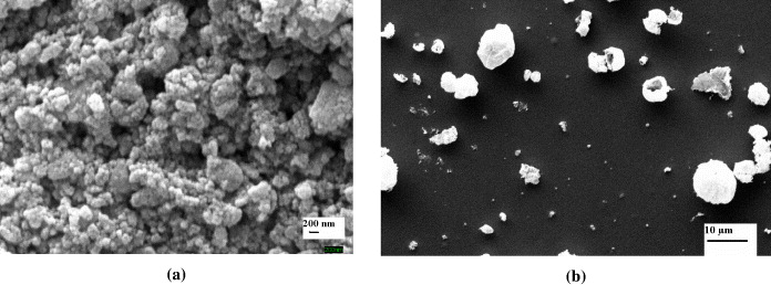
Figure 1 SEM images of (a) ZnO nanoparticles collected from outlet, (b) ZnO film on untreated ITO substrate.
Figures 2(a) and 2(b), respectively, show the SEM images of the sample deposited on pre-treated ITO substrate for 15 min and cross section of ZnO nanorods. The images clearly indicate that substrate pre-treatment is required for nanorod growth. It can be concluded that the substrate pre-treatment plays a key role for highly oriented ZnO nanorod growth.

Figure 2 SEM images of (a) pre-treated ITO; (b) cross-section of ZnO nanorods (t dep =15 min).
Simple gas flow and water droplets spray was also tried in order to test the real cause of nanorod growth. It was found that there was no nanorod growth in these two cases which suggests that Zn availability in the precursor to be sprayed (in addition to substrate pre-treatment) is necessary for the nanorod growth.
3.2. Effect of deposition time
A set of samples was deposited on pre-treated substrates with deposition time (t dep ) changed from 5 to 25 min. The SEM images for this set of samples are shown in figure 3. It can be seen that, as time of deposition increases, surface coverage becomes more uniform. For 5 min there are several islands on the surface with some flower-like nanostructures and also some very fine nanorods can be seen. As the deposition time is increased to 10 min, the uniformity of surface coverage is improved and there are fewer islands on the surface. For 15 min, the nanorods uniformly covered the entire surface. By further increasing the time to 20–25 min, some closed networking of the nanoparticles over the nanorods started appearing. For lower deposition time, the density of islands on the substrate is much higher, but at higher times, the density of islands becomes small and the nanorods uniformly cover the surface. From figure 3(f), one can see that the ZnO film deposited for 15 min has a hexagonal column structure.
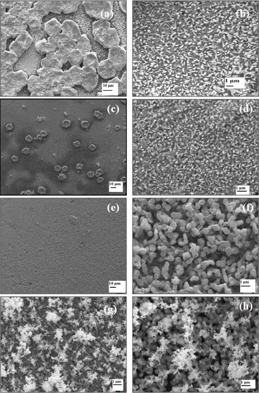
Figure 3 SEM images of ZnO nanorods grown at 5 min (a and b), 10 min (c and d), 15 min (e and f), 20 min (g) and at 25 min (h).
The crystallinity and crystal phase of the ZnO nanorods were studied by XRD patterns (figure 4). Figures 4(a) and 4(b) show typical XRD pattern for the ZnO nanoparticles collected from the outlet and nanorods (t dep =15 min), respectively, with high-purity wurtzite hexagonal phase and all of the diffraction peaks match well with standard hexagonal ZnO (a=3.249 Å and c=5.206 Å, JCPDS 36-1451). The ratio of lattice constants, c/a, was found to be around 1.60 which is consistent with values of the bulk wurtzite ZnO. The relative intensity ratio between (002) and (101) diffraction peaks is usually used to characterize the orientation of ZnO nanorods. In comparison with the standard card, the peak intensity of (002) is stronger than that of (100), indicating the (001) oriented growth of the ZnO nanorods.
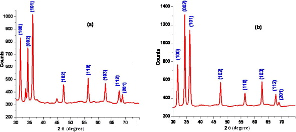
Figure 4 XRD images of (a) ZnO nanoparticles collected from outlet, (b) nanorods deposited for 15 min.
It is reported that when the Zn precursor coated film is annealed at a higher temperature (250 °C), ZnO seeds are formed and most of (0001) planes of these particles prefer to be parallel to the substrate [48]. The seed layer formed on the ITO substrates offers nucleation sites for the nanorods. The nanorods grown from these ZnO seeds with the (0001) planes parallel to the substrate will be perpendicular to the substrate.
Figure 5 shows the 1.5 μm×1.5 μm AFM image of the samples deposited for 5 min and 15 min. From this image it can be seen that with increase in deposition time, the density as well as the thickness of the nanorods increases. The lengths of ZnO nanorods can be controlled by changing the duration of deposition time. The average diameter of ZnO nanorods is found to increase from 100 to 600 nm and their heights from 50 nm to 2 μm as the deposition time is increased from 5 to 15 min. Roughness analysis shows that the surface roughness also increases with deposition time. For 5 min, roughness (rms) is around 14 nm, whereas for 15 min, it is 150 nm.
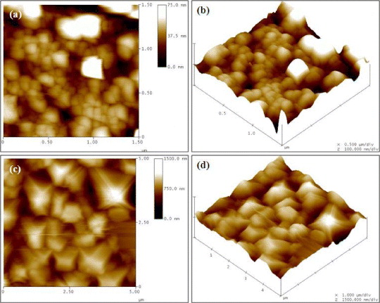
Figure 5 AFM images of ZnO nanorods for t dep as 5 min (a and b) and 15 min (c and d).
To prepare TEM samples, ZnO nanorods (t dep =15 min) were scraped from the ITO substrate and were dispersed in ethanol to make a solution. One drop of this solution was dropped on carbon coated Cu grid for TEM scanning. The corresponding TEM images and selective area electron diffraction (SAED) for individual ZnO nanorod are shown in figure 6.
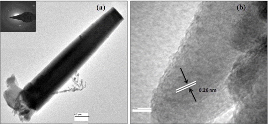
Figure 6 (a) TEM and (b) HRTEM images of a single ZnO nanorod.
The TEM images indicate that the as-deposited ZnO nanorod is single-crystalline ZnO with a wurtzite structure grown along the (001) direction, which is consistent with the XRD results. The ZnO nanorod in the corresponding HRTEM image (figure 6(b)) exhibits clear lattice fringes with lattice spacing of 0.26 nm, corresponding to the (002) lattice spacing of a hexagonal ZnO crystal. It suggests that they are single crystals, consistent with the XRD analysis. The ZnO nanostructure grows preferentially along [001] direction because of the lowest surface energy of (001) facet [49]. The growth velocity along [101] directions is slower than that along [001] direction, so that the pillar morphology is often obtained. Therefore, the nanorods expectedly grew along the [001] direction.
When the spray deposition was carried out for 5–10 min, the initial steady reaction favored the longitudinal growth, but as soon as the precursor flow was stopped after 5 and 10 min, the production of the new ZnO species was reduced, causing a reduction in the dimensions, giving nanorods of smaller height. But when the spray was continued for a sufficient time (12–15 min), the longitudinal growth continued to form the ZnO nanorod arrays. For even higher times (20–25 min), large quantities of ZnO nanoparticles are still arriving at the third zone. These ZnO nanoparticles could not be absorbed by the ZnO nanorod growth front because of the unavailability of any further ZnO nucleation site on the substrate; instead these nanoparticles are deposited on top of the nanorods. As can be easily seen in the SEM image, there is a closed networking of nanoparticles that starts appearing over nanorod growth after 20 min.
Thus, the above discussion reveals that by simply controlling the deposition time (t dep ), we can control the morphology, size and density of ZnO nanorods. Figure 7 shows a schematic of the ZnO nanorods' growth mechanism with Zn solution providing the seed layer.
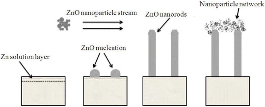
Figure 7 Schematic of the ZnO nanorods' growth mechanism with Zn solution providing the seed layer.
To study the optical absorption of the ZnO nanorod film, the samples were soaked in 0.3 mM of 'black dye' (N-749, Solaronix) in ethanol solution for 6 h, at room temperature. Then the dye-adsorbed films were immersed immediately into the dehydrated ethanol to remove the excess dye. Figure 8(b) shows the optical absorption spectrum of the unmodified and dye modified ZnO nanorod film (t dep =15 min). The spectra clearly show the enhancement in absorbance of the dye-modified films compared to that of the unmodified films which confirms a better light-scattering/light-harvesting efficiency. Figure 8(a) shows the optical absorption spectrum of the dye detached from the nanorod film. The spectrum shows the peaks at 410 and 610 nm that correspond to black dye [50].
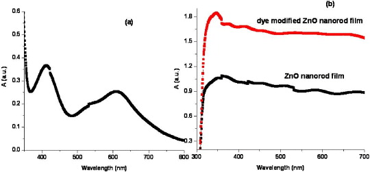
Figure 8 Optical absorption spectra of (a) detached dye from nanorod film, (b) unmodified and dye modified ZnO nanorod film (t dep =15 min).
The detailed procedure for the fabrication of ZnO dye-sensitized solar cells is described in the experimental section. The current density–voltage (J–V) characteristics of ZnO DSSCs with varying deposition time of ZnO layer is shown in figure 9 and summarized in table 1. From the plot it is evident that, the conversion efficiency of the cell increases from 1.6 to 1.77% when the t dep is increased from 10 to 15 min, but thereafter it decreases to 1.49 and 1.23% for t dep as 20 and 25 min, respectively. The increase in the efficiency is due to the increase in the nanorod length (from A to B) which provides a large amount of surface area, more adsorbed dyes, resulting in higher conversion efficiency. But, the nanorod length increases only up to t dep =15 min beyond which, because of the unavailability of ZnO species at the substrate, close networking of nanoparticles takes place over the nanorods. Thus the decrease of the conversion efficiency for C and then further for D may be attributed to the close networking of nanoparticle growth over the complete vertical nanorods (as can be seen in the SEM image), whereas for B, the response is completely due to the vertical nanorod arrays (height greater than A). The presence of nanoparticles contributes to the number of grain boundaries/inter-particle states, which act as electron traps [51].
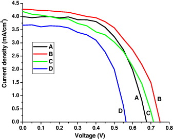
Figure 9 J–V characteristics of ZnO nanorod DSSC showing the effect of deposition time.
Table 1. Photovoltaic parameters of ZnO nanorod based DSSCs.
| A | 10 | 4.0 | 0.67 | 0.60 | 1.60 |
| B | 15 | 4.30 | 0.75 | 0.55 | 1.77 |
| C | 20 | 4.2 | 0.71 | 0.50 | 1.49 |
| D | 25 | 3.66 | 0.56 | 0.60 | 1.23 |
4. Conclusion
In summary, ZnO DSSCs have been fabricated using nanostructured films grown using continuous spray pyrolysis (CoSP) reactor. The technique provides one of the fastest routes to synthesize ZnO nanorods. It has been demonstrated that the substrate pre-treatment conditions help in the creation of self-assembled one-dimensional nanostructures, and also the time of spray has a strong influence on controlling the density of the ZnO nanorods. The ZnO-nanorods-based DSSC with a layer thickness of ∼2 μm yielded a conversion efficiency of 1.77% which is higher than the ones reported for the same photoelectrode thickness.