
Abstract
Anodic aluminum oxide (AAO) nano-templates are used in many fields of nanotechnology, particularly for use in creation of nanowires and nanotubes. In this research, the method for fabricating AAO nano-templates in two different electrolyte solutions (sulfuric acid and oxalic acid) via two step anodization procedure is presented. The influence of parameters related to both anodization steps such as the electrolyte, solution temperature, voltage and time on the pore size, porous distance and pore density was investigated. Scanning electron microscopy (SEM) images of the nano-templates also pointed out the effectiveness of this anodization method. The synthesis of carbon nanostructures from a polymeric precursor such as epoxy via fully filling the nanoporous AAO templates is reported. The prepared nanowires and nanotubes have been characterized by transmission electron microscopy (TEM), Raman spectroscopy and SEM. The results show the typical morphology and properties of multiwall carbon nanotubes and other nanostructures.
Export citation and abstract BibTeX RIS

Content from this work may be used under the terms of the Creative Commons Attribution 3.0 licence. Any further distribution of this work must maintain attribution to the author(s) and the title of the work, journal citation and DOI.
1. Introduction
Anodic aluminum oxide (AAO) template, also well known as AAO membrane, exhibits the morphology of hexagonally arranged parallel pores. It is a self-organized nanostructured material containing a high density of uniform cylindrical pores that are aligned perpendicularly to the surface of the material and penetrate its entire thickness. The pores can easily be controlled between 5 and 400 nm in diameter and several tens of micrometers in depth. Therefore, nanoporous anodic aluminum oxide has been employed to synthesize a variety of nanostructured materials such as nanowires, nanorods and especially nanotubes [1–6]. The anodic aluminum oxide fabrication technique is one of the key methods for the fabrication of nano channel arrays. Most recent published studies [2, 4, 5, 7–11] have used the two-step method using the same type of electrolyte solution. Thus, the pore size depends on the conditions of both anodization steps: type of acid, applied voltage, temperature and time.
Since 1990 many scientists have succeeded in preparing tubular nanostructures or fiber from a variety of different precursor materials to create nanostructures such as metal fibers and CNT by this method. Polymeric nano-structures such as nanorods, nanowires and nanotubes can be manufactured by wetting and fully filling the nano-pores of AAO templates with polymer solutions or polymer melts before carbonization and graphitization.
2. Experimental
2.1. Materials
All of the chemical compounds, perchloric acid, ethanol, sulfuric acid, oxalic acid, epoxy DER 331 and curing agent DETA, were purchased from Merck. The AAO templates were fabricated from plates (30 mm × 40 mm × 0.3 mm) of 99.95% pure aluminum.
2.2. Fabrication process of carbon nanostructures
2.2.1. Manufacturing of AAO nanopore templates.
The fabrication process of AAO templates is described in figure 1.
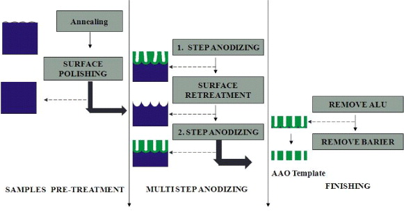
Figure 1. Schema of AAO template fabrication.
Download figure:
Standard image High-resolution imageThe aluminum plates are annealed at 550 °C for 180 min to remove internal stresses and increase the crystallization of aluminum [5, 6, 10]. The electrochemical polishing of aluminum sheets in a mixture of perchloride acid and ethanol (HClO4 (70%): C2H5OH = 1:4 by volume) under 15 V dc for 10 min was performed in order to remove surface impurities. The surface structure of the aluminum sheets after the electrochemical polishing is shown in figure 2. The two-step anodization follows the pretreatment process to create the nano-pores.

Figure 2. The light microscopic images of the aluminum surface after treatment.
Download figure:
Standard image High-resolution imageIn this experiment, the first-step anodization was carried out using a 3 wt% sulfuric acid solution at a voltage of 12 V at 2 °C in 120 min. In this step, the surfaces will be etched to remove the faults and heterogeneous oriented pore's structures are formed on the surface.
The aluminum oxide layer was removed via chemical etching in a mixture of 6 wt% of phosphoric acid and 1.8 wt% of chromic acid at 60 °C [2, 4, 5, 7–11]. Subsequently, on the aluminum surface there are honeycomb-like structures with relatively uniform diameters, shapes and surface distribution (figure 3). These structures are pore nuclei directing the pore growth in the second anodization step.
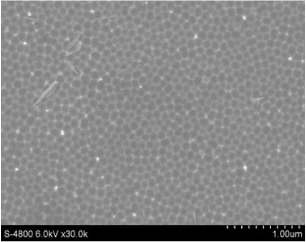
Figure 3. FE-SEM images of the aluminum surface after removing of the aluminum oxide layer.
Download figure:
Standard image High-resolution imageThe goal of the second anodization step is to enlarge pores in depth as well as in diameter uniformly. Thus, the electrolyte used in this step should fulfill two conditions: no or low heat released and fast growth of the pore depth. Oxalic acid as electrolyte is a good choice as the anodization released low heat, and the relative growth rate of the pore diameter is slower than that of the pore depth. The influence of second-step conditions, such as temperature (at 0.3 M oxalic acid, 40 V, 120 min), voltage (0.3 M oxalic acid, 5 °C, 120 min) and time (0.3 M oxalic acid, 40 V, 5 °C) on the structure of AAO template was studied.
2.2.2. Fabrication of polymer and carbon nanostructures.
The process to form the nanostructures is illustrated in figure 4. Nanopores of the AAO templates can be filled with a precursor polymer solution or hot-melt polymer using various physical sorption techniques such as dipping, reverse osmosis, dripping and vacuum pumping. After solvent removal, the epoxy resin was cured to form polymeric nanotubes in the AAO template, which was recovered by dissolving the AAO template in a strong acid. The subsequent carbonization of the polymeric nanotubes at 700–1000 °C under inert atmosphere was performed to yield CNTs or carbon nanofibers.
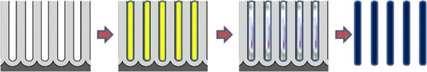
Figure 4. Steps to form the polymeric nanostructures.
Download figure:
Standard image High-resolution image2.2.3. Methods of characterization.
Optical microscopy was used to characterize the surface structure of aluminum sheets. Scanning electron microscopy (SEM) was used to analyze the AAO template structure. Transmission electron microscopy (TEM) and Raman spectroscopy were used to characterize the synthesized nanostructures.
3. Results and discussion
3.1. Manufacturing of AAO nanopore templates
Figure 5 shows the surface structure of the AAO template obtained via a two-step procedure: the first anodization in a sulfuric acid solution and the second anodization in an oxalic acid solution with optimum conditions summarized in table 1 and the morphology of the pore's wall is presented in figure 6.
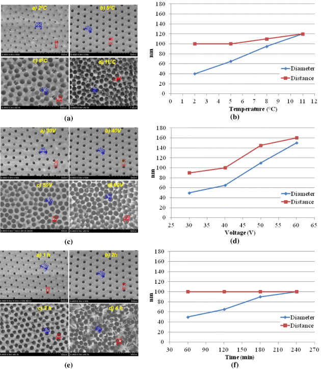
Figure 5. Influence of different conditions in second anodization step on morphologies of AAO template surfaces (a,c,e), on pores diameter and on distances between pores centers (b,d,f).
Download figure:
Standard image High-resolution image
Figure 6. Morphologies of the pore's wall.
Download figure:
Standard image High-resolution imageTable 1. Fabrication conditions for AAO templates.
| First anodization step in sulfuric acid | Second anodization step in oxalic acid | ||||||
|---|---|---|---|---|---|---|---|
| Concentration (%) | Temperature (°C) | Voltage (V) | Time (h) | Concentration (M) | Temperature (°C) | Voltage(V) | Time(h) |
| 3 | 2 | 12 | 1 | 0.3 | 5 | 40 | 2 |
3.2. Effect of wetting methods on properties of polymeric structures
3.2.1. Immersion the AAO template in epoxy/methylethylketon (MEK) solution.
Figures 7 and 8 show the SEM and TEM images, respectively, of the polymeric structures via dipping the AAO templates in epoxy/MEK solution.
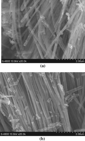
Figure 7. SEM images of nano structures by immersion methods into epoxy/MEK solution 5% (a) and 10% (b).
Download figure:
Standard image High-resolution image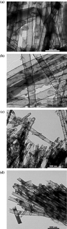
Figure 8. TEM images of nano structures by immersion methods into epoxy/MEK solution 5% (a), 10% (b), 15% (c) and 20% (d).
Download figure:
Standard image High-resolution imageThe products contained both nanotubes and fibers with a lot of defects generated during the solvent evaporation inside the tubes, however, with nanotubes as the majority. Upon increasing the epoxy concentration, the content of defects decreased, as a result of an enhanced resin AAO template adhesion and reduced formation of voids upon solvent evaporation.
3.2.2. Reverse osmosis method.
SEM (figure 9) and TEM (figure 10) images show the polymeric structures, synthesized by reverse osmosis methods. The products contained both nano-tubes and fibers. Upon increasing the epoxy concentration, the tube wall thickness increased and the content of nanofibers also increased.
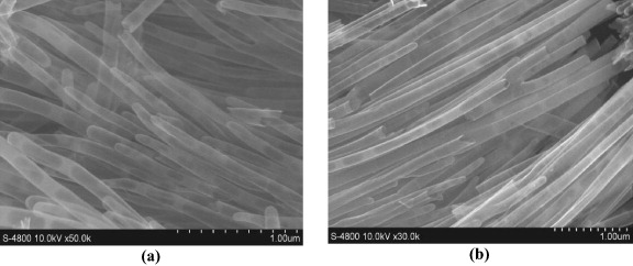
Figure 9. SEM images of nano structures by reverse osmosis methods with epoxy/MEK solution 5% (a) and 10% (b).
Download figure:
Standard image High-resolution image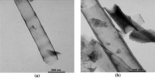
Figure 10. TEM images of nano structures by reverse osmosis methods with epoxy/MEK solution 5% (a) and 10% (b).
Download figure:
Standard image High-resolution image3.2.3. Filling the nanopores by epoxy-melt.
Figure 11 shows SEM and TEM images of the polymeric structures synthesized by the pore-filling method. The products comprised most of the nanotubes with relatively uniform tube wall thicknesses and the tube surface containing few defects.
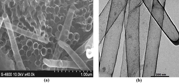
Figure 11. SEM (a) and TEM (b) images of nano structures by epoxy melt filling methods.
Download figure:
Standard image High-resolution imageFrom the results of using different nanopore-filling methods, the use of a molten epoxy resin allowed a considerable formation of nanotubes with better shape and size compared to the other approaches. The obtained nanotubes had diameters of 120–150 nm, with quite uniform wall thicknesses and smooth surface.
3.3. Carbonization and graphitization of nanostructures
As above-mentioned, the use of a molten epoxy was the most suitable method for nanopore-filling of the AAO template. In these experiments, the temperature for carbonization of the epoxy nanotubes was studied at 700, 800, 900 and 1000 °C with a heating rate of 2 °C min−1 in 3 h.
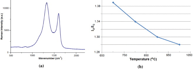
Figure 12(a) presents the Raman spectra of the nanotubes carbonized at 1000 °C with characteristic D and G peaks at approximately 1350 and 1600 cm−1, providing ID/IG ratios of the intensities ID and IG of these characteristic D and G peaks as a measure of the amount of disorder in the CNTs. However, it should be noted that the carbon nanotubes obtained by this method have graphite layers in turbostratic structures which are different from the structures of carbon nanotubes fabricated by other methods. Figure 12(b) shows the decrease of ID/IG ratio values by increasing of carbonization temperature.
Figure 12. Raman diagram of carbon nanotubes at carbonization temperature 1000 °C (a) and ID/IG values at carbonization temperature 700, 800, 900 and 1000 °C (b).
Download figure:
Standard image High-resolution image
4. Conclusions
The AAO nanotemplates were successfully fabricated. The pore diameter and density can be controlled by applying voltage, temperature, time and electrolyte. Using these templates, nanostructures including epoxy nanotubes, carbon nanotubes and carbon fibers were obtained.
Acknowledgment
The authors acknowledge the financial support from the Department of Science and Technology of Ho Chi Minh City.