
Abstract
Time-resolved photoluminescence (TRPL) and photostability were studied for several core/shell-type semiconductor quantum dots (QDs) of CdTe/CdS, In(Zn)P/ZnS and CdZnS/ZnS using a TRPL microscopy at a single QD level, of which results were compared to that of CdSe/ZnS QD. The CdTe/CdS and In(Zn)P/ZnS QDs show unstable PL at a single QD level on both bare and polymer-coated glass coverslips, so that they mostly lose emissions within a few seconds. The CdZnS/ZnS QD shows better emission stability than those of the former two QDs, but still less stable than the case of the CdSe/ZnS.
Export citation and abstract BibTeX RIS

Content from this work may be used under the terms of the Creative Commons Attribution 3.0 licence. Any further distribution of this work must maintain attribution to the author(s) and the title of the work, journal citation and DOI.
1. Introduction
Semiconductor quantum dots (QDs) have attracted great attention because of the distinctive advantages of tunable band-gap energy, high emission yield and tailorable surface chemistry [1]. Meanwhile, photoluminescence (PL) intermittency, i.e. on/off blinking behavior, prevents them from use for a number of potential application fields. To date, PL blinking is considered to be due to Auger recombination of (charged) excitons and/or a recombination through surface trap states [2, 3]. By modification of QD surface with organic or inorganic component, PL blinking behavior can be manipulated to obtain more stable emission.
For the last decade, PL blinking behavior has been investigated mostly on II–VI semiconductor QDs and nanorods [4, 5]. Limited studies accomplished to prepare blinking free CdSe QDs with high emission stability by changing core composition and/or applying proper surface modification [6, 7]. In particular, the fabrication of heavy metal-free QDs is also of great interest due to involving cytotoxicity issues [8, 9]. Hence, it is very challenging work to fabricate high-quality heavy metal-free QDs and to study their photostability.
In this work we have fabricated monodisperse cadmium-free In(Zn)P/ZnS core/shell QDs. Steady-state PL, time-resolved PL and on/off blinking characteristics were investigated using single molecule spectroscopy. The results are discussed in comparison with other II–VI semiconductor QDs such as CdTe/CdS, CdZnS/ZnS and CdSe/ZnS QDs.
2. Experimental
2.1. Chemicals
Cadmium bromide (CdBr2), 3-mercaptopropionic acid (MPA), mercapto succinic acid (MSA), indium acetate, myristic acid, tris(trimethylsilyl) phosphine (PTM)3S), zinc chloride, potassium ethylxanthate, dimethyl formamide (DMF), tri-n-octylphosphine (TOP), 1-octadecene (1-ODE), oleic acid (OA), oleylamine(OLA), octylamine, tributylphosphine (TBP), zinc acetate (Zn-(acet)2), sulfur, selenium shots, acetone, methanol, ethanol, chloroform, toluene and n-hexane (all anhydrous) were purchased from Sigma-Aldrich. Cadmium oxide (CdO), bisdimethyldithiocarbamic acid zinc salt (Zn(DMTC)2) and zinc stearate (ZnSt2) were purchased purchased from Acros, TCI and Riedel de Haën, respectively. Sodium borohydride (NaBH4), tellurium powder (Te) and thiourea (NH2)2CS) were purchased form Merck. All the chemicals were used without further purification.
2.2. Preparation of core/shell In(Zn)P/ZnS QDs
Briefly, the In(Zn)P/ZnS QDs were synthesized in 1-octadecene solution with the presence of zinc stearate (the Zn2+:In3+ molar ratio of 1:1), the reaction temperature for forming the core and the shelling temperature were fixed at 300 and 285 °C, respectively. In(Zn)P/ZnS QDs has a more pronounced excitonic absorption peak and strong, rather narrow luminescence were observed at 443 and 510 nm, respectively. The high quantum yield reaches up to ∼ 70%.
2.3. Preparation of core/shell CdTe/CdS QDs
CdTe/CdS core/shell QDs were prepared with Cd:Te molar ratio of 10:1, the reaction temperature for forming the core and the shelling temperature were fixed at room temperature and 120 °C, respectively. As-prepared CdTe/CdS core/shell QDs exhibit a bright green emission at ∼ 540 nm under room light.
2.4. Preparation of core/shell CdZnS/ZnS QDs
CdZnS/ZnS core/shell QDs were prepared following a previous report [10]. Typically, 1 mmol of CdO, 10 mmol of Zn(acet)2 and 7 ml of OA was placed in a round flask. After heating this solution to 300 °C, 2 mmol of sulfur dissolved in 3 ml of 1-ODE was quickly injected into the reaction flask, and reaction temperature was maintained at 300–310 °C to grow core QDs. After 10 min QD growing, 8 mmol of sulfur dissolved in TBP was injected into the reaction flask to overcoat the core QDs with ZnS shell.
2.5. Preparation of core/shell CdSe/ZnS QDs
Core CdSe QD was prepared by reacting in situ-generated cadmium oleate (Cd(OA)2) with TOPSe at a high temperature. Typically, 1 mmol of CdO and 3 mmol of OA were heated to 200 °C to form a transparent solution. After cooling to room temperature (RT), 10 ml of ODE and 6 mmol of OLA were added. After heating to 300 °C, 2 ml of 1.0 M TOPSe, prepared by reacting TOP with Se, was quickly injected. The temperature was decreased to 280 °C for the growth of QD. After cooling to RT, the solution was treated with hexane and ethanol to separate the QD from the unreacted precursors. This separation process was repeated three times. CdSe QD was finally precipitated with excess acetone. The CdSe QDs thus prepared were highly soluble in common non-polar organic solvents, such as hexane, chloroform and toluene. To coat with ZnS layer on the core CdSe QDs, 1 ml of 1 M Zn(DMTC)2 in octylamine was added into the crude CdSe reaction solution at RT. The temperature was slowly increased to 150 °C and the reaction mixture was maintained at that temperature for 10 min to grow the ZnS shell.
2.6. Instrumentations
Steady-state absorption and emission spectra of the bulk QD solutions were measured using a UV–Vis absorption spectrophotometer (Scinco S-3100) and a photoluminescence spectrophotometer (Hitachi F-7000). Hexane is used as solvent for In(Zn)P/ZnS, CdZnS/ZnS and CdSe/ZnS QDs, while the CdTe/CdS QDs are dissolved in water. Time-resolved PL (TRPL) imaging at a single particle level was performed using an inverted-type scanning confocal microscope (Picoquant MicroTime-200) with a 100 × oil-immersion objective. A single-mode pulsed diode laser (with a 375 nm output and an instrumental response function of ∼ 240 ps in full-width at half-maximum, a 5 MHz repetition rate and an average power of less than 1 μW) was used as an excitation source. A dichroic mirror (z375RDC, AHF), a long-pass filter (HQ405lp, AHF), a 50 μm pinhole and a single-photon avalanche diode were used to collect the emissions from semiconductor core/shell QDs that were spin-coated onto glass coverslips. Time-resolved PL decay curves were obtained from time-intensity profile data measured at a focused confocal volume, and PL lifetimes were evaluated using the commercial SymPhoTime software (ver. 5.1.3) by a three-exponential decay model.
3. Results and discussion
The prepared semiconductor core/shell QDs are type I of which core QD is covered with semiconductor shell having larger band-gap than that of the core semiconductor. Distinct excitonic absorptions appear at blue-shifted region compared to the bulk band-gaps (1.48, 1.34 and 1.90 eV) of the CdTe, InP, CdSe QD cores, respectively (figure 1) [11]. The CdZnS/ZnS QDs show gradually increasing absorption with a band-edge at ∼ 470 nm which is located between the bulk band-gaps (2.50 and 3.68 eV) of the CdS and ZnS, respectively [11]. The observed emission spectra appear nearby the excitonic absorptions or absorption edges of the core/shell QDs without any notable emission at the longer wavelength region below the band-gap, except for the In(Zn)P/ZnS QDs. In the case of the In(Zn)P/ZnS QDs, the observed emission tail in the longer wavelength region is responsible for a minor route of electron–hole recombination through surface electronic states of the core QDs.

Figure 1. Absorption and emission spectra of (a) the CdTe/CdS, (b) In(Zn)P/ZnS (c) CdZnS/ZnS, and (d) CdSe/ZnS QDs. Excitation wavelengths are (a–c) 380 and (d) 550 nm.
Download figure:
Standard image High-resolution imageFor the core/shell QDs of different compositions, we measured TRPL decays for the bulk solutions. Figure 2 shows interesting TRPL decays for the QDs. Each decay curve is fitted by two or three exponential decay models to evaluate PL lifetimes for the QDs, of which fitted parameters are shown in table 1. One obvious difference is shown in the InP/ZnS QDs at a glance. The observed PL lifetime is much shorter than those of the other QDs. The relatively shorter lifetime indicates that the In(Zn)P/ZnS QDs have additional recombination routes, such as through surface electronic states, which agree with the observation of the steady-state emission tail. The CdZnS/ZnS and CdSe/ZnS QDs are reasonably fitted to enable three lifetime components. Interestingly, the CdTe/CdS QDs have two lifetime components without a fast component within a few nanoseconds.
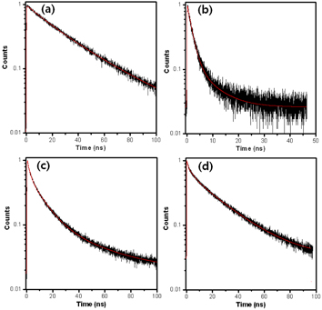
Figure 2. Time-resolved PL decays of (a) the CdTe/CdS, (b) In(Zn)P/ZnS, (c) CdZnS/ZnS and (d) CdSe/ZnS QDs in bulk solution. The red line is a fitted line.
Download figure:
Standard image High-resolution imageTable 1. Fluorescence lifetimes of the core/shell QDs in solution.
| Sample | A1 (%) | τ1 (ns) | A2 (%) | τ2 (ns) | A3 (%) | τ3 (ns) | 〈τ〉 (ns)a | χ2 |
|---|---|---|---|---|---|---|---|---|
| CdTe/CdS | – | – | 39 | 17.11 | 61 | 37.10 | 29.34 | 1.2 |
| In(Zn)P/ZnS | 83 | 1.58 | 17 | 6.67 | – | – | 2.42 | 1.0 |
| CdZnS/ZnS | 44 | 1.70 | 46 | 10.31 | 10 | 39.46 | 9.42 | 1.1 |
| CdSe/ZnS | 22 | 0.63 | 22 | 4.40 | 56 | 25.00 | 15.19 | 1.1 |

We studied TRPL characteristics for the core/shell QDs at a single QD level (table 2). Spin-coated QDs on a glass coverslip are far apart from each other so that focused confocal volume contains single QD, which is probed by the well-known CdSe/ZnS QDs. Figure 3(k) shows CdSe/ZnS QDs on a glass coverslip. The observed PL intensity trace with time shows characteristic on/off blinking signals for a single QD (figure 3). Such PL blinking is often observed from semiconductor QDs because of Auger recombinations within a QD or plausible recombinations through surface electronic states [2,3]. In spite of the blinking behavior, the CdSe/ZnS QDs are shown to have relatively long lifetime compared to the others due to high population in 'on' time. The CdZnS/ZnS QDs show lower population of 'on' time so that the lifetime is shorter than that of the CdSe/ZnS QDs. Interesting points are observed from the single CdTe/CdS and In(Zn)P/ZnS QDs. The lifetime of the single CdTe/CdS QDs is dramatically shortened, while the In(Zn)P/ZnS QDs show similar lifetimes compared to the corresponding bulk solutions. From the time-dependent PL intensity traces of the InP/ZnS QDs, it is consistently observed that PL is just on within a few seconds right after the laser light irradiated (figure 3(e)). However, it does not be detected any distinct 'on' state emission for the CdTe/CdS QDs, but mostly shows weak remnant PL trace (figure 3(b)). The instability of the PL from single CdTe/CdS QDs seems related to the charge state of QDs that prevents the 'on' state after the electron and hole are photogenerated by the laser light excitation.
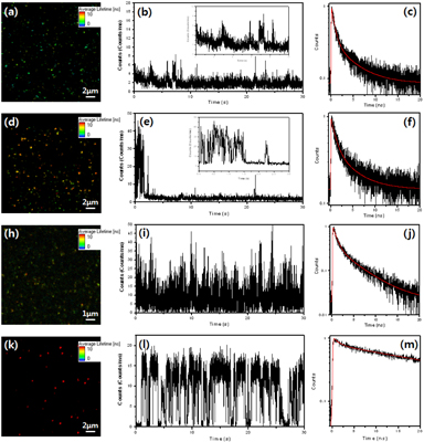
Figure 3. (a,d,h and k) Time-resolved PL images, (b,e,i and l) intensity-time profiles and (c,f,j and m) emission decays of the CdTe@CdS, In(Zn)P@ZnS, CdZnS@ZnS and CdSe@ZnS QDs, respectively. The red line is a fitted line.
Download figure:
Standard image High-resolution image
4. Conclusion
We studied time-resolved PL characteristics and photostability for CdTe/CdS, In(Zn)P/ZnS and CdZnS/ZnS QDs at a single QD level. Compared to the well-known CdSe/ZnS QDs, the CdTe/CdS and CdZnS/ZnS QDs easily tend to lose their emissions at a single QD level and, therefore, have comparatively shorter PL lifetimes than those from the bulk solutions. However, the In(Zn)P/ZnS QDs have consistency on PL lifetime in both cases of solution and a single QD. Interestingly, the CdTe/CdS and In(Zn)P/ZnS QDs show very unstable emissions at a single QD level, turning shortly to 'off' state within a few seconds. The reason for the extremely weak photostability of the PL from single QDs is still unknown. But these results would be very helpful to enhance the photostability for the QDs, enabling more 'on' state, which would be broadly applicable to a number of application fields such as biological labeling, cell imaging, sensors, solar cells, photonics, optoelectronics, etc.
Acknowledgments
This work was supported by a National Research Foundation (NRF) grant no. 2011-0008671 and an International Joint Research Program (F32603) by KBSI, and by National Foundation for Science and Technology Development (NAFOSTED) grant no. 103.03.35.09. The authors thank Dr Yun Ku Jung for the supported CdSe/ZnS QDs.