

Abstract
Pt nanoparticles on vulcan XC-72R support (Pt/vulcan XC-72R) were prepared by the impregnation–reduction method. The Pt content, the morphological properties and the electrochemical catalysis of the Pt/vulcan XC 72R materials have been investigated by ICP-OES analysis, FESEM, TEM, and cyclic voltammetry. These materials were then used as catalyst for hydrogen evolution reaction at the cathode of proton exchange membrane (PEM) water electrolysers. The best catalyst was Pt/vulcan XC-72R prepared by the impregnation–reduction method which is conducted in two reducing steps with the reductants of sodium borohydride and ethylene glycol, respectively. The current density of PEM water electrolysers reached 1.0 A cm−2 when applying a voltage of 2.0 V at 25 °C.
Export citation and abstract BibTeX RIS

Original content from this work may be used under the terms of the Creative Commons Attribution 3.0 licence. Any further distribution of this work must maintain attribution to the author(s) and the title of the work, journal citation and DOI.
1. Introduction
Proton-exchange membrane (PEM) water electrolysis can contribute to the development of a hydrogen infrastructure network [1–3]. Hydrogen can be produced efficiently using electricity from renewable energy sources such as solar and wind [1, 2, 4]. In conventional PEM water electrolysers, precious metals have been used as electrocatalysts such as platinum or palladium at the cathode for the hydrogen evolution reaction (HER) and iridium (or its oxides) at the anode for the oxygen evolution reaction (OER) [1, 2, 5]. One of the main challenges in PEM technology is minimizing of noble metal loading in PEM cell without decreasing its efficiency and lifetime. This can be achieved by using the electrocatalysts consisting of the nanoparticles of the noble metals on the low-cost electronic carriers with large surface area [1, 2]. The platinum and palladium nanoparticles supported by vulcan-XC 72 [1] or graphitic nanofibers [2] have been successfully used as electrocatalysts at the cathode for HER. However, it is not easy to fabricate the noble metal nanoparticles spreading on the whole surface of the carbon carriers because the surface area of the carbon carriers is very large, e.g. 170 m2 g−1 and 250 m2 g−1 for graphitic nano-fibers and vulcan XC-72R, respectively. To date, the impregnation–reduction method has been considered as the best method to prepare the noble metal nanoparticles on carbon carriers. There are some impregnation–reduction methods using different reductants such as formaldehyde (FD) [1, 2], ethylene glycol (EG) [6], and sodium borohydride (SB) [7].
Therefore, the aim of this study is screening and improving the impregnation–reduction method to prepare the platinum nanoparticles on vulcan XC-72R carrier which is suitable to use as electrocatalyst at the cathode of the PEM water eletrolysers.
2. Experimental
2.1. Material
Vulcan XC-72R carbon powder was purchased from Cabot Corporation (USA). Other chemicals, namely sulfuric acid (98%), nitric acid (65%), hydrochloric acid (37%), hydrogen peroxide (30%), potassium hydroxide, sodium hydroxide, sodium borohydride, chloroplatinic acid hexahydrate (H2PtCl6 · 6H2O), iridium(III) chloride hydrate (IrCl3 · xH2O), ethylene glycol, ethanol, acetone, nafion 117 solution (5 wt.%) and nafion 117 membrane were purchased from Sigma-Aldrich Corporation (USA). De-ionized water (millipore) with 18 MΩ cm−1 resistivity was used throughout all the experiments.
Iridium oxide was prepared from IrCl3 · xH2O by thermal decomposition method [5, 8]. Then, iridium black catalyst was prepared by reducing the colloid of iridium oxide (diameter about 200 nm, figure 1) in water with the excess of sodium borohydride. The reduction was carried out overnight under continuous stirring. The stirring was switched off and the precipitate of iridium black is obtained by centrifuging.
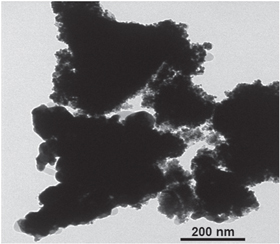
Figure 1. TEM image of Ir-black.
Download figure:
Standard image High-resolution image2.2. Synthesis of the electrocatalysts
2.2.1. Ethylene glycol reductant
Platinum nanoparticles deposited onto vulcan XC-72R carrier were synthesized by the impregnation–reduction method with ethylene glycol (EG) reductant, described by Kumar et al [6]. Briefly, the vulcan XC-72R carbon powder (255 mg) was dispersed with 70 ml of EG in a three-neck flask by a magnetic stirring bar. Then 35 ml of 0.025 M H2PtCl6 solution in water was added drop wise into the dispersion under continuous stirring. The pH of this mixture was adjusted to about 9 by 1 M KOH solution. After that, the mixture was refluxed at 110 °C for 3 h and stirred overnight under atmosphere of nitrogen. The resultant Pt40/C (E) catalyst (where 40 denotes the content (wt.%) of platinum, C denotes the vulcan XC72R carbon carrier and E denotes EG reductant) was washed several times by water and acetone and dried at 80 °C in an oven.
2.2.2. Formaldehyde reductant
With formaldehyde (FD) reductant, the impregnation–reduction method was carried out as described by Grigoriev et al [1, 2]. In brief, 255 mg of carbon was dispersed in 30 ml of EG by sonicating. Then 8.7 mL of 0.1 M H2PtCl6 aqueous solution was added drop wise into the dispersion under continuous stirring. The pH of the mixture was adjusted to about 9 by 1 M KOH solution then 110 mL of EG was added to the mixture. The reduction was initiated by stirring and pre-heating the dispersion to 75 °C. After adding 87 ml of a FD solution (37%) drop wise into the dispersion, the temperature of the mixture was kept at 95 °C for 3 h. Then the heating was switched off and the dispersion was cooled down to ambient temperature for 2 h under continuous stirring. The remaining deposit was washed with water (7 to 8 times) by centrifuging. Then, it was dried at 70 °C. As a result, Pt40/C (F) catalyst (F denotes FD reductant) was obtained.
2.2.3. Sodium borohydride reductant
With sodium borohydride (SB) reductant, the synthesis method was done as described by Sung et al [7]. Briefly, 255 mg of carbon was dispersed in 200 mL water by stirring and sonicating. Then 8.7 mL of 0.1 M H2PtCl6 aqueous solution was added drop wise into the dispersion under continuous stirring. Then, metal precursors were reduced by the excess of SB, which was added drop wise into the dispersion (5 times larger than the stoichiometric amount of metal precursors). The obtained Pt40/C (B) catalyst (B denotes SB reductant) was washed by water several times and dried by freeze-drying without any heat treatment.
2.2.4. Step-by-step sodium borohydride and ethylene glycol reductants
Step 1: The Pt25/C material (where 25 denotes the content (wt.%) of platinum) was synthesized by the impregnation–reduction method with SB reductant, as described by Sung et al [7].
Step 2: Platinum nanoparticles were adhered further to the Pt25/C material by the impregnation–reduction method with EG reductant, as described by Kumar et al [6].
The resultant Pt40/C (B–E) catalyst (where 40 denotes the content (wt.%) of platinum and B–E denotes the synthesis method using two reducing steps with SB and EG reductants) was washed several times with water and acetone and then dried at 80 °C in an oven.
2.3. Characterization of catalyst particles
The content (wt.%) of platinum in the catalyst particles was measured by an inductively coupled plasma optical emission spectrometry (ICP-OES), Perkin Elmer, Optima 8300 according to ISO 11494:2008. Briefly, 10 mg of the catalyst particles was digested with 40 ml of aqua regia by heating gently until complete dissolution. After cooling, the sample was marked up with water to 100 ml and mixed thoroughly. Then the concentration of platinum in sample solution was determined.
The surface morphology of the catalyst particles was examined by a field emission scanning electron microscope (FESEM), Hitachi, S-4800 and a transmission electron microscope (TEM), JEOL, JEM-1400.
Electrochemical characterization was performed by cyclic voltammetry on a typical three-electrode cell. Working electrodes were prepared as follows [1, 2]: 2 mg of the catalyst particles was mixed with 20 μL of 5 wt.% alcoholic solution of nafion and 800 μL ethanol by sonicating for 30 min. Then 5 μL of the mixtures was spread on the glassy carbon disk (diameter of 6.5 mm) of the working electrode. Slurries were then dried at 75 °C in an oven. Ag/AgCl, 3 M KCl and a platinum wire were used as reference and counter electrodes, respectively. Cyclic voltammograms were recorded in de-aerated 1 M H2SO4 by a cyclic voltammetry, Bio-Logic-Science Instruments, VMP-300. Electrode surfaces were first activated by cycling with scan rate 20 (mV s−1) in the potential range −0.225 to + 1.275 V versus Ag/AgCl, 3 M KCl to obtain stable and reproducible voltammograms.
Electrochemically active surface areas (EAS) of the Pt40/C catalysts were estimated from the cyclic voltammograms by the method as described by Grigoriev et al [1, 2].
2.4. PEM electrolysis cell
PEM electrolysis cells were prepared by using nafion-117 membrane as solid electrolyte [5, 9]. The Nafion-117 membranes (178 μm in thickness and 2 × 2 cm2) were first cleaned by the process of Du Pont. The membranes' impurities were washed out with water, then with 3% hydrogen peroxide and finally with 0.5 M sodium hydroxide solution. The cleaning processes were accelerated by heating at 80 °C for 1 h. Then, the membranes' alkaline residual was rinsed out by hot water.
The inks of the cathode catalysts were prepared as follows: 1.25 mg of the Pt/vulcan XC-72R catalysts were mixed with 100 μL ethanol, 100 μL water and 10 μL of 5 wt.% alcoholic solution of nafion by sonicating for 30 min. The inks of the anode catalysts were prepared as follows: 2.50 mg of the Ir-black powder was mixed with 100 μL ethanol and 10 μL 5 wt.% alcoholic solution of nafion by sonicating for 30 min.
The watery nafion 117 membranes were clamped tightly by two polystyrene tablets (1 cm in thickness and 4 × 4 cm2), each tablet has a rounded hole with the cross area of 1.0 cm2. The cathode catalyst ink and the anode catalyst ink were spread, respectively, onto the uncovered area of two opposite sides of the nafion 117 membranes and dried at 85 °C. The electrocatalyst layers were adhered tightly onto the nafion 117 membranes by a hot pressing process. The membranes supported electrocatalysts were sandwiched between two sheets of teflon (1 mm in thickness and 3 × 3 cm2) and pressed at 50 kg cm−2, then heated gently to 150 °C for 30 min. Then the electrocatalysts supported membranes were boiled in 1 M sulfuric acid solution for 30 min and residual acid was washed off by hot water.
The two platinized titanium micro grids (1 mm in thickness and 1.2 × 1.2 cm2) were placed as current distributor on both sides of the membranes supported electrocatalysts and two titanium sheets (1 mm in thickness and 1.2 × 4 cm2) were used as end plates. The above items were clamped together with two polystyrene end plates (1 cm in thickness and 4 × 4 cm2). The 1.0 cm2 single electrolysis cells were immersed in water sink. The current–voltage curves were recorded at 25 °C.
3. Results and discussion
3.1. The Pt content
The Pt content of the obtained Pt40/C catalyst is able to significantly affect its electrocatalyst [9]. In the impregnation–reduction, the formation of the Pt nanopaticles in the bulk solution makes the Pt content in the catalysts lower. The experiment result (table 1) shows that the Pt content in the obtained Pt40/C catalysts efficiency of the deposition Pt on vulcan XC-72R increases with the strength of the reductant (EG < FD < SB) and the surface tension of the solvent (EG < EG/H2O < H2O).
Table 1. The Pt content in catalysts.
| Catalyst | Reductant | Solvent | Pt content, % |
|---|---|---|---|
| Pt40/C (E) | EG | EG | 33.6 ± 2.1 |
| Pt40/C (F) | FD | EG/H2O | 36.2 ± 1.8 |
| Pt40/C (B) | SB | H2O | 37.1 ± 2.6 |
| Pt40/C (B-E) | SB—EG | H2O—EG | 39.1 ± 2.3 |
In addition, the Pt content of the Pt40/C (B–E) catalyst is highest (table 1) and reaches 97.75% of the Pt content calculated following the total amount of the loading Pt (IV) salt. Therefore, the impregnation–reduction method will get the higher efficiency of the deposition Pt on vulcan XC-72R when the loading Pt (IV) salt is decreased. However, with the lower loading of Pt (IV) salt, the impregnation–reduction method has to be carried out several times to reach the Pt content desired.
3.2. Morphological characterization
In aiming to fabricate the Pt/C catalysts compared to the Pt black catalyst powder, the Pt nanoparticles should be distributed over the entire surface of the carbon carrier in tiny and homogeneous size. Experimentally, platinum can be distributed over the entire surface of the carbon carrier when the concentration of chloroplatinic acid has to be high enough during the impregnation step, which in turn yields the Pt nanoparticles of large size. The Pt nanoparticles of large size were observed by FESEM images (figure 2), while the distribution of the Pt nanoparticles of small size on the surface of the carbon carrier were illustrated by TEM images (figure 3).
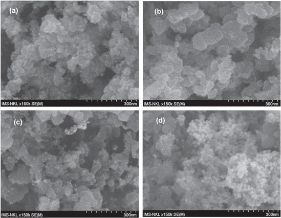
Figure 2. FESEM image of catalyst: (a) Pt40/C (E); (b) Pt40/C (F); (c) Pt40/C (B) and (d) Pt40/C (2S).
Download figure:
Standard image High-resolution image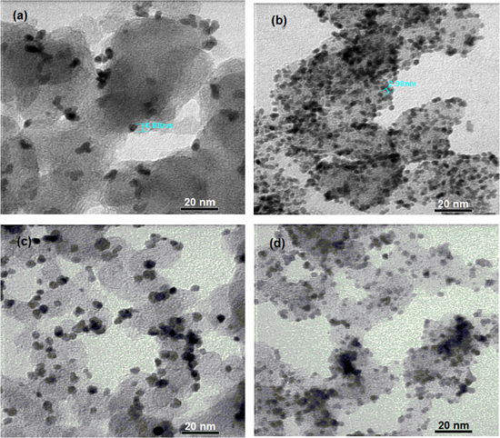
Figure 3. TEM images of catalysts: (a) Pt40/C (E); (b) Pt40/C (F); (c) Pt40/C (B) and (d) Pt40/C (B–E).
Download figure:
Standard image High-resolution imageFESEM and TEM images show that the Pt40/C (E) and Pt40/C (B) catalysts consist of many Pt nanoparticles in large size (figures 2(a) and (c)); the diameter of the Pt nanoparticles of small size is above 5 nm and the coverage ratios of Pt nanoparticles is not high (figures 3(a) and (c)).
Although the Pt nanoparticles of large size exist little in the Pt40/C (B-E) catalyst (figure 2(d)), the diameter of the Pt nanoparticles of small size is below 3 nm and the coverage ratios of Pt nanoparticles are quite high (figure 3(d)). Therefore, the decreasing of the loading of Pt (IV) salt also helps to lessen the diameter of the Pt nanoparticles on vulcan XC-72R.
On the other hand, the Pt40/C (F) catalyst only consists of a few Pt nanoparticles in large size (figure 2(b)), the diameter of the Pt nanoparticles of small size is about 3 nm and the coverage ratios of Pt nanoparticles are quite high (figure 3(b)). Following image analysis, the Pt40/C (F) catalyst can be the best of the obtained catalysts. This obtained result is similar to the result reported by Grigoriev et al [1]. The preeminence of FD reductant may be due to the absorption of FD on the Pt cluster [10] forming in the impregnation–reduction process. This absorption may prevent the Pt cluster from the size increasing.
3.3. Electrochemical characterization
Cyclic voltammograms recorded on the working electrode, which is the glassy carbon electrode, are modified by the thin film of the Pt40/C catalysts and nafion binder. These cyclic voltammograms are shown in figure 4. The cyclic voltammetry curves of the Pt40/C catalysts are similar to that of Pt black powder catalyst (figure 4). Therefore, the Pt40/C catalysts are expected to behave as Pt black powder catalyst for the HER.
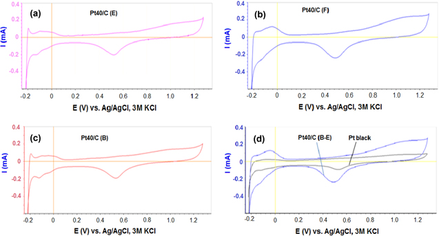
Figure 4. Cyclic voltammograms recorded on electrodes modified by (a) Pt40/C (E), (b) Pt40/C (F), (c) Pt40/C (B) and (d) Pt40/C (B-E) and Pt black in 1 M H2SO4 at 25 °C, scan rate 20 mV s−1.
Download figure:
Standard image High-resolution imageElectrochemically active surface areas (EAS) of the Pt40/C catalysts were estimated from the cyclic voltammetry curves in figure 4. The EAS of the Pt40/C (F) catalysts is similar to the result obtained by Grigoriev et al [1]. The EAS of Pt40/C (F) catalysts is the same as that of the Pt40/C (B–E) catalyst and higher than those of the Pt40/C (E), Pt40/C (B) or Pt black catalysts (table 2). Therefore, to enhance the EAS of the catalysts, the impregnation–reduction method is necessary to use FD reductant or decrease the loading of Pt (IV) salt in each impregnation–reduction step.
Table 2. The EAS of catalysts.
| Catalyst | Reductant | Solvent | EAS (m2 g−1) |
|---|---|---|---|
| Pt black | — | — | 16.5 ± 2.0 |
| Pt40/C (E) | EG | EG | 27.0 ± 2.5 |
| Pt40/C (F) | FD | EG/H2O | 37.0 ± 3.0 |
| Pt40/C (B) | SB | H2O | 25.5 ± 2.5 |
| Pt40/C (E-B) | SB-EG | H2O-EG | 35.5 ± 4.0 |
3.4. Water electrolysis
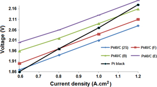
During PEM water electrolysis, the typical current–voltage curves are recorded at 25 °C and plotted in figure 5. All our PEM water electrolysers illustrated the current density of 1.0 A cm−2 when the applied voltages were about 2.0 V. So our PEM water electrolysers operate similarly to those designed by Grigoriev et al [11]. Their conversion efficiency reaches about 75% at 1.0 A cm−2 and 25 °C. Therefore, their conversion efficiency can show the cathodic catalysis of the synthesized Pt40/C catalyst.
Figure 5. I–V polarization curves measured on a 1.0 cm2 single electrolysis cell at 25 °C and atmospheric pressure. Cathodic catalyst: Pt40/C (2S), Pt40/C (F), Pt40/C (B), Pt40/C (E) and Pt black (1.25 mg cm−2). Anodic catalyst: Ir black (2.5 mg cm−2).
Download figure:
Standard image High-resolution image
The PEM electrolyser with the Pt40/C (B-E) catalyst at cathode offers the best efficiency (figure 5) in comparison with those with the other Pt40/C or Pt black catalyst at cathodic cathode. Cathodic catalysis of the Pt40/C (F) catalyst was a little lower than the Pt40/C (B–E) catalyst, although the Pt40/C (F) and Pt40/C (B–E) catalyst possess the same EAS. This unexpected behavior could result from the absorption of FD on the Pt nanoparticles of Pt40/C (F) catalyst [10]. Further study should be carried out to clarify this phenomenon.
4. Conclusions
The results show that Pt40/C (F) has the highest coverage ratio and the Pt nanoparticles are almost those of homogeneous size while the Pt40/C (B-E) catalyst has the highest cathode catalysis. These results lead to the conclusion that the impregnation–reduction method consisting of two steps with the Pt loading about 20% of carbon weight per step is a promising approach for the preparation of the cathodic catalysts which possess Pt nanoparticles on vulcan XC-72R carrier.
Acknowledgments
This work is financially supported in part by the Department of Science and Technology of Ho Chi Minh City, Vietnam.