

Abstract
Biosensors have been rapidly developed recently. Biological receptors, such as antibodies, must be immobilized on these sensors' surfaces to make the sensor capable of capturing a target analyte. In this research we studied how to modify a gold-coated surface of a microcantilever, a sensor with high potential in biological and medical applications. Thiol chemistry was adapted to create a cysteamine layer on a gold surface, and subsequently glutaraldehyde was used as a cross-linking agent to react with amine groups in receptors. In order to evaluate the efficiency of immobilizing protein on an Au surface and also whether the protein retains its biological activity, horseradish peroxidase enzyme (HRP) with its activity to catalyze a reaction between 2,2'-azino-bis [3-ethylbenzothiazoline-6-sulphonic acid] (ABTS) and  was used as a testing protein. The result showed that HRP was immobilized successfully on cysteamine and glutaraldehyde layers and retained its activity. The cantilever's tip deflection was also measured, and results showed that each layer created surface stress and made the cantilever bend—in particular, the cysteamine layer induced bending as high as 6 μm. An antibody of alpha-fetoprotein (AFP) was immobilized on the cantilever surface, and the measurement deflection showed that the sensor responded to solution containing AFP with concentration from 100 to 500 ng ml−1.
Export citation and abstract BibTeX RIS

Original content from this work may be used under the terms of the Creative Commons Attribution 3.0 licence. Any further distribution of this work must maintain attribution to the author(s) and the title of the work, journal citation and DOI.
1. Introduction
With the development of micro/nano fabrication techniques and molecular biology, the two fields are being combined in research and development to offer a massive array of biosensors. Today medical diagnosis can be carried out in a simple way and by normal people, thanks to such biosensors. Glucose sensors, pregnancy tests and cholesterol sensors are being developed and commercialized. These sensors include a small surface on which a biological receptor is immobilized, and will react with the target molecules in the patient's blood. In the case of a gold electrode sensor used to detect glucose, glucoxidase and peroxidase are immobilized; the first enzyme catalyzes the transformation of glucose and creates H2O2, the second enzyme catalyzes the reduction of H2O2 and the electron is transferred to the gold electrode, creating electric current. In the case of a micro cantilever, the upper surface contains an immobilized antibody; when the cantilever is immersed into human serum or blood, the antibody will capture the corresponding biomarker and the cantilever bends up or down due to the surface stress created in the biomarker layer. A biosensor based on surface plasmon resonance also has a gold surface attached with an antibody.
The microcantilever chip has increasingly attracted attention from researchers as a sensor with diversifying application, such as a gas sensor, bacteria sensor [1, 2], drug discovery [3], explosive detection [4], etc. Craighead et al [1] in 2011 first demonstrated the ability to detect Escherichia coli bacteria using a microcantilever, and then in 2003 the detection of Salmonella enterica was announced [2]. In the publication regarding the detection of S. enterica, the stress on the cantilever surface changed when the binding event happened, and then caused the cantilever to bend.
The advent of antibiotic-resistant bacteria, including methicillin-resistant Staphylococcus aureus and vancomycin-resistant Enterococcus, stimulated the interest to study how antibiotics work and why they fail to suppress these bacteria. One suggestion is that the bacteria change their cell wall peptide to become resistant to vancomycin [3], according to research by McKendry et al [5]. In this research, they studied the interaction between vancomycin with two peptides: the vacomycin-sensitive and vancomycin-resistant peptide; by coating a cantilever chip with a vancomycin-sensitive peptide or vancomycin-resistant peptide, they were able to determine the binding constants between vancomycin and two kinds of cantilever, and observed that vancomycin could not bind with a vancomycin-resistant peptide.
Material for a cantilever is often silicon or silicon nitride. Each cantilever chip has a single or multiple cantilevers. For a microcantilever chip, each cantilever length and width are in the 100 micrometer range, and the thickness is several micrometers, while a nanocantilever chip has a cantilever length and width in tens of micrometer range and a thickness of typically 100 nm. The cantilevers are often coated with a thin layer of gold, typically 20 nm, in order to reflect the laser beam shining upon it during measurement. Each time a new layer of molecules is formed on the cantilever gold surface, it creates surface stress and induces the cantilever to bend. In order to measure the bending, a laser beam is shone upon the cantilever length and reflected on the position-sensitive detector (PSD). A measurement computer system has an actuator to drive the laser head and scan the laser beam along the cantilever length, and then collect data from the PSD. The data can then be processed to calculate the deflection of the cantilever. The bending of the cantilever is often proportional to the amount of molecules immobilized on it, and depends also on the interaction between the molecule. The interaction between the molecules, either through electrostatic force, hydrophobic force or Leonard–Jones interaction (or combined) [5–7] may create compressive stress or tensile stress, thus making the cantilever bend up or down.
In this paper, cantilever chips made of silicon nitride and coated with Au were studied. Thiol chemistry was adapted. This method involved binding cysteamine to the gold surface, and then glutaraldehyde (GAD) was introduced, and a reaction between the aldehyde group of GAD with the amine group of cysteamine formed a new layer of GAD on the Au surface. Thanks to the other free aldehyde group of GAD, the Au surface then became very chemically active towards the amine group, thus being able to capture protein on the Au surface. Horseradish peroxidase (HRP), an enzyme capable of catalyzing a reaction between various pairs of substrates and H2O2, was immobilized on this amine-reactive surface. The chip was then immersed into a solution containing reduced 2,2'-azino-bis [3-ethylbenzothiazoline-6-sulphonic acid] (ABTS) (colorless) and H2O2, and HRP on the chip catalyzed the oxidization-reduction between ABTS and H2O2. ABTS changed its state into an oxidized state, in which it had a green color. Using this method, we proved that our modification steps can be used to immobilize protein on an Au surface and still retain the activity of the protein.
We immobilized the antibody of alpha-fetoprotein (AFP) by this method, and then immersed the cantilever chips into a solution containing AFP. Using a system equipped with a laser, head, actuator and PSD, we were able to measure the change in cantilever deflection after each step of surface modification, and thus cross-check the existence of each molecule layer on the cantilever. With this measurement method, we also saw a relationship between the cantilever bending and the concentration of AFP in phosphate buffered saline (PBS).
2. Experimental
Silicon nitride cantilever chips were fabricated in the Laboratory for Nanotechnology (LNT), National University in Ho Chi Minh City, Vietnam. Each chip contained 9 cantilevers, whose length, width and thickness are 500, 100 and 1 μm, respectively. The base of the chip was silicon with a dimension 4 × 2 × 0.38 mm3. On the upper face of the cantilever, a thin layer of titanium and gold (20 nm) was coated (figure 1).

Figure 1. Structure of microcantilver chip (a) and its image under scanning electron microscope (b).
Download figure:
Standard image High-resolution imageThe chip was first cleaned in acetone and ethanol to remove dirt and contaminants. In order to modify the Au surface, cysteamine (Sigma) was dissolved into ethanol (Merck) and then the chip was immersed in the 5 mM cysteamine solution at room temperature for 16 h. After that the chip was rinsed with ethanol to remove physically adsorbed cysteamine, and then was immersed in glutaraldehyde (Sigma) dissolved in deionized water (final concentration 2.5%). After this step, the Au surface contained aldehyde groups and thus became very reactive towards amine groups, and protein such as HRP, an antibody of AFP or bovine serum albumin (BSA) could be immobilized on it.
In order to verify that protein could be immobilized on this activated surface, and also that the protein's biological activity was intact after immobilization, we used HRP (Sigma). The chip was immersed into 10U of HRP solution in PBS at 4 °C for 16 h. After that the chip was rinsed with PBS again to remove physically adsorbed HRP, leaving only HRP chemically bound to the aldehyde groups. A working solution contains unoxidized ABTS (which is colorless) and H2O2 (1 mM:1 mM) in PBS pH 7.4 was prepared. The chip was immersed into the working solution and a green color developed; this color is due to the absorbance in the optical visible spectrum of oxidized ABTS, proving that HRP on the cantilever surface still retained catalytic activity. We used Cary100 at LNT to measure the absorption spectrum of the working solution in the visible region.
In order to study the cantilever response with AFP, we treated the chips with cysteamine, GAD, and then immersed the chips into anti-AFP diluted to 5 μg ml−1 in PBS buffer (at 4 °C, overnight). The antibody used in this paper is IgG monoclonal antibody from a mouse (Insight Genomics Inc., USA) raised against human AFP. The chips were then taken out and rinsed with PBS again and put into Scala to measure deflection. After that, the chips were immersed into BSA (Sigma) in PBS (2% weight/weight, at room temperature, for 30 min). This protein was used to block all aldehyde groups that did not react with anti-AFP and may react with AFP, giving rise to a false positive signal. The chips were taken out, rinsed with PBS and deflection was measured again. Finally the chips were immersed in AFP (Insight Genomics Inc.) 500 ng ml−1 in PBS at room temperature for 2 h, rinsed and deflection was measured again.
The optical reflectance method to measure cantilever bending was carried out using the Scala system supplied by Mecwins, Spain. This system has a PC-controlled actuator to move a red laser on the XY plane (horizontal plane). The chips were put into a measurement chamber, which can hold up to nine chips. The actuator can move the laser head with high speed (up to 10 mm s−1) and high precision (micrometer resolution) in the XY plane, and scan the entire measurement chamber. The laser beam makes an angle of 45° with the XY plane. A PSD detector was put on the opposite side of the laser head to collect the reflected beam, and outputs signal to the Scala. The Scala processed the signal and calculated the deflection of the cantilevers. Each experiment was carried out with one chip, because each chip has nine cantilevers and averaged deflection can be collected from the measured data.
3. Results and discussion
3.1. Evaluating surface modification using HRP
In this experiment we prepared four experiments (A1, A2, A3 and A4) with a working solution (ABTS + H2O2). Nothing was immersed into the cup of experiment A1 (negative control solution). In cup A2, one cantilever chip was immersed on which HRP was immobilized. In cup A4, 10U of HRP was dropped directly into it. In cup A3, a chip which was previously immersed in HRP solution (this chip had not undergone cysteamine/GAD treatment) was immersed. Each experiment was carried out on three chips and the averaged intensity of adsorption intensity was calculated and shown in table 1.
Table 1. Absorption intensity of working solutions after 24 h.
| Experiment | Description | Absorption intensity |
|---|---|---|
| A1 | Negative control | 0.004 ± 0.003 |
| A2 | Immersed chips with Cysteamine/GAD/HRP | 0.110 ± 0.017 |
| A3 | Immersed chips with HRP | 0.009 ± 0.004 |
| A4 | Positive control | 2.813 ± 0.224 |
After 24 h the solution in A1 was still transparent, no color developed. In A2 the solution turned green and in A4 the solution turned dark green. The result in A1 proved that without the existence of peroxidase, ABTS and H2O2 almost did not react with each other. The A4 dark green color proved that 10U HRP catalyzed the reaction very rapidly, and the A2 green color proved that the HRP was immobilized on the chip and catalyzed the reaction, though not very rapidly.
The UV–vis spectrum of four solutions gave us more quantitative data. The absorption of A1 at 420 nm is 0.004, which is very small, around 1/700 times compared to the absorption of A4. For A2, the absorption at 420 nm is 0.11, small compared to A4's absorption, but was still 27 times that of A1. The result indicated that HRP was successfully immobilized on the cantilever chip, but the amount was not as many as 10U of the HRP droplet. This is understandable, because during the experiment, the cantilever chip was immersed into 10U of HRP solution; due to the small area of the nine cantilevers, only a very small amount of HRP was immobilized on the surface, the remaining was washed away in the rinsing step. One more reason is that HRP on cantilevers cannot move freely in the solution, thus ABTS and H2O2 must diffuse towards the cantilever's surface for the reaction to be catalyzed. In short, the reaction in A2 was not only limited by the small amount of HRP on nine cantilevers, but also limited by the diffusion velocity of the reactants.
Figure 2 shows the absorption spectra in the visible region of the control solutions and solutions with cantilever chips.
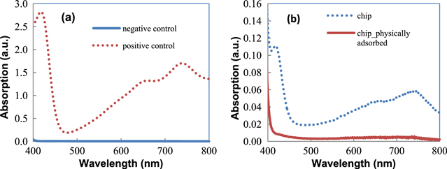
Figure 2. Absorption spectra in the visible region of (a) control solutions and (b) solutions with cantilever chips.
Download figure:
Standard image High-resolution imageOne may doubt that cysteamine and GAD were not successfully formed on the Au surface, and HRP on the cantilever chip in the A2 cup could have bonded with the cantilever surface through physical adsorption. In order to verify this, the A3 experiment was conducted: the cantilever chip was cleaned, and the chip was immersed directly into 10U of HRP solution for 16 h at 4 °C. In this way, there were no cysteamine and GAD treatment steps, so the HRP did not bond to the cantilever surface via the chemical reaction between the CHO and NH2 groups, but instead physically adsorbed directly on the Au surface. The physical bonding is known to be weaker than chemical bonding, and the adsorbed species can easily desorb. After immersion in HRP, the chip was taken out and then rinsed thoroughly in PBS. The solution (ABTS + H2O2) cup A3 containing this chip did not change color after 24 h, at least under the naked eye. In the absorption spectrum of A3, the intensity at 420 nm was only 0.008, which was stronger than that of the negative control (about twice) but was only 1/13 compared to that of A2.
The results stated above suggest to us that HRP could be physically adsorbed on the cantilever chip, but thanks to the rinsing step, most of the HRP would be washed away. On the other hand, the chip in the A2 experiment, in which cysteamine and GAD treatment were performed, had HRP chemically bound onto it, and these HRP would not be washed away in the rinsing step.
In general, the results proved that cysteamine and GAD were formed successfully on the Au surface, and protein immobilized on it did not desorb easily. What is more important is that the biological activity of HRP, which is its catalytic ability, is still retained.
At this point we would like to discuss the conditions for HRP to retain its activity after being captured on the Au surface with the aldehyde group. This means that the bonding between the protein and aldehyde must be chemical bonding, which was strong enough to keep the protein on the surface, yet such bonds did not alter the three dimensions configuration of protein, or deactivate important parts of the protein. Three-dimensional (3D) configuration was known to be vital for the protein's activity: a denatured protein molecule loses its activity even when the peptide chain is intact.
HRP is an enzyme with a complex structure; its main function, which is to catalyze the reaction between the reduced substrate and H2O2, requires the combined action of the hemeprosthetic group, substrate binding pocket and H2O2 binding pocket. Figure 3 depicts HRP structures and components [8], figure 3(a) shows the 3D structure of HRP protein, with the heme prosthetic group lying at the center (carbon: white; oxygen: red; nitrogen: blue and Fe: magenta). The heme prosthetic group, depicted separately in figure 3(c), is ferriprotoporphyrin IX (2, 7, 12, 18-tetramethyl-3,8-divinylporphine-13, 17-dipropionic acid). Its main function is to create the bonding between the iron FeIII and one of the two oxygen atoms in H2O2. The H2O2 binding pocket, as its name implies, captures the H2O2 molecule and facilitates the abstraction of the H2O2 proton [9, 10], and also the cleavage of O–O bonding. This pocket includes acid amine residues Arg38, Phe41 and His42, which lie in the vicinity of the heme prosthetic group (as depicted in figure 3(b)). Changing these residues, especially His42, will drastically reduce the catalytic activity of HRP, down to 5 orders of magnitude [11, 12]. Also, His42 must be close enough to the heme prosthetic group so that it could facilitate the abstraction of proton when the H2O2 is being held by FeIII. Asn70 must be at the correct position to form a hydrogen bond with His42. This bond increases the basic role of His42 which is important for the acid-basic catalytic reduction of H2O2 [13, 14]. The substrate binding pocket includes Phe68, Phe142 and Phe179 residues, which enable the binding of aromatic substrates [15], and Leu138, Pro139, Ala140, Pro141 and Gly69 contribute to building the channel for the substrate to approach the heme prosthetic group.
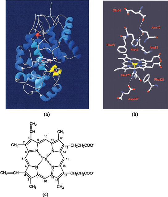
Figure 3. (a) 3D structure of HRP, (b) heme prosthetic group surrounded by important acid amine residues and (c) formula of the heme prosthetic group.
Download figure:
Standard image High-resolution imageThe reaction between the substrate and H2O2 can only happen when all of these events in HRP happen successfully, meaning that the HRP's 3D structure must be intact after immobilization on a solid surface, or at least does not change significantly.
Anti-AFP specifically, and antibodies in general, need to maintain their 3D structure in order to bind efficiently with antigen. The binding regions in an antibody (Ag binding region) are found at the amino termini of VH/VL pairs (herein VH refers to the variable domain in the heavy chain, and VL refers to the variable domain in the light chain). The Ag binding region contains about 50 acid amine residues, forming many paratopes to recognize epitopes on the antigen. Each paratope contains about 15 acid amine residues, which are not close to each other when the protein is not folded or denatured, but are brought close together when the protein folds. Epitope and paratope are complementary parts of each other, regarding shape and electric charge, therefore only when the Ag binding region is in its correct 3D structure shall the antibody capture the antigen efficiently (there are some techniques to use papain or pepsin to cleave the disulfide bond between two halves of an antibody, after which the Ag binding regions on each half of the antigen are still intact and can be used in a biosensor [16]).
Therefore, the antibody may be immobilized on Au using the cysteamine/GAD surface modification protocol mentioned above, with high probability that the antibody can keep its biological activity (that is to capture its corresponding antigen, or biomarker).
3.2. Evaluating the surface modification by measuring deflection
3.2.1. Deflection of a cantilever after each surface modification step
In this experiment we measured the deflection of the cantilevers after each step of surface modification: after cleaning the chips, after treating with cysteamine, after treating with GAD, after treating with an antibody of AFP, after treating with BSA, and after treating with AFP.
In this experiment we used seven chips. Chip S1 underwent all modification steps: treatment with cysteamine, GAD, anti-AFP, BSA and AFP. The other five chips, symbolized from REF1 to REF5 were used as reference samples: chip REF1 was cleaned and immersed in cystemine 0 mM (only ethanol), and its differential deflection was only zero (0043 μm). Chip REF2 was treated with cysteamine, and was then immersed in GAD 0% (only water) and its differential deflection was 0.032 μm. All other reference chips had the same results: the cantilevers' differential deflections were almost zero. Table 2 shows the differential deflection for all reference chips (REF chips) and chip S1 after each modification step.
Table 2. Differential deflection of reference samples and chip S1 after each modification step.
| Step | Differential deflection (μm) | |
|---|---|---|
| REF chips | S1 chip | |
| After cysteamine | 0.043 ± 0.056 | 6.481 ± 0.057 |
| After AGD | 0.032 ± 0.043 | 0.119 ± 0.099 |
| After anti-AFP | 0.075 ± 0.072 | 1.399 ± 0.106 |
| After BSA | 0.055 ± 0.034 | 0.060 ± 0.066 |
| After AFP | 0.048 ± 0.033 | 0.722 ± 0.067 |
Chip S1's cantilever all bent up with deflection changing drastically after it was treated with cysteamine (more than 6 μm). Cysteamine is a bifunctional linker—the functional thiol group SH is at one end, and the functional amine group is at the other end. The hydrocarbon chain of one cysteamine can interact with the hydrocarbon chain of another cysteamine if they can be brought close enough. Some research groups studied the formation of a cysteamine layer on gold, and came to the conclusion that cysteamine molecules exist in the form of a self-assembled monolayer. The reaction can be divided into two stages [17]. In the first stage, the thiol group of cysteamine quickly reacts with gold to form a stable bond between S and Au (sulfur, selenium have strong affinity with transition metal) [18, 19]. At this stage the direction of cysteamine on Au is random and there is no interaction between adjacent cysteamine because the density of cysteamine is not high enough. In the second stage, when the surface density of cysteamine becomes high, the adjacent hydrocarbon chains begin to interact with each other through van der Waals force or other interactions, and the orientation of the cysteamine molecules becomes more uniform and the degree of order increases. It has been known that the axis of a hydrocarbon chain tilts 26–28° from the normal Au surface [17]. After this stage a large surface stress is formed within the cysteamine layer.
After being treated with GAD, S1's cantilevers did not behave uniformly in this experiment. The average differential deflection is only −0.119 μm, which was smaller than even the deviation of measurement (0.1 μm). The reason behind this may be a very small surface stress created in the GAD layer. Perhaps GAD only reacted with amine groups but the interaction between each GAD was so weak that it did not lead to a self-assembled monolayer with high order. GAD might have arbitrary orientation on the Au surface.
After anti-AFP was immobilized on chip S1, the cantilever all bent up (differential deflection 1.399 μm), proving the existence of a new layer of molecules which had formed on the Au surface. The differential deflection was not as large as that after cysteamine treatment. The reason for the smaller deflection may be that high surface stress only exists in a densely packed self-assembled monolayer, where molecules are very close to each other and interact so strongly that the random orientations rearrange to approach a uniform angle. Antibodies are not known to form self-assembled monolayers, and their orientations are random on the surface (some even bury their antigen-binding region beneath and cannot capture biomarkers). Therefore, an antibody layer may create small or moderate surface stress.
BSA is also a protein, and the surface stress it created was also not large, as shown from the data: S1's cantilevers bent only 0.06 μm, with a deviation 0.066 μm. Because the measurement error was even greater than the measured differential deflection, we could not tell whether BSA had reacted with the residual aldehyde group or not. Perhaps in the previous step, with a high concentration of anti-AFP (5 μg ml−1) and a long reaction time (16 h), anti-AFP had already covered most of the cantilever, and there were not many residual CHO left. Some BSA might have reacted and blocked the residual CHO groups, but the density of BSA was very low and the additional surface stress it created was very small compared to that of anti-AFP. Moreover, the surface stress it created may not be attributed to the interaction between BSA molecules only, because the Au surface already contained a lot of anti-AFP molecules, thus BSA molecules was more likely to be surrounded by and interact with anti-AFP.
Finally, when AFP was captured by anti-AFP in the final surface modification step, a new surface stress appeared and caused S1's cantilevers to bend. This stress caused moderate bending of the cantilevers (0.722 μm), which is much larger than bending due to GAD or BSA layers, but smaller than stress due to the anti-AFP layer and cysteamine layer. This is very promising, because we can use it to detect AFP and quantify its concentration in PBS.
3.2.2. Deflection of cantilever versus AFP concentration and standard curve
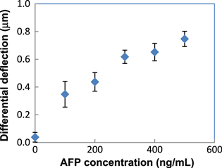
After using the Scala system to measure the differential deflections and prove the success of each surface modification step, we then proceeded to research the experimental relation between differential deflection and concentration of AFP in PBS. Five chips were immobilized with anti-AFP (5 μg ml−1) and BSA (2%) and then were put into the Scala system to measure the deflection. After that, they were immersed in five PBS solutions with 0, 100, 200, 300, 400, 500 ng ml−1 of AFP. After 2 h they were taken out and rinsed with PBS, and the Scala system was used to measure the deflection again. Each chip had nine cantilevers, so the differential deflections of nine cantilevers on one chip were averaged to give the averaged differential deflection corresponding to that chip, and also corresponding to the concentration of the AFP solution.

Figure 4. Deflection of cantilevers after each step of surface modification.
Download figure:
Standard image High-resolution imageFigure 4 shows the deflection of chip S1 after each modification step. Figure 5 shows the differential deflections of the chips after immersion in AFP with different concentrations. Chips immersed in 0 ng ml−1 of AFP (it means this chip was immersed in PBS only) had the averaged differential deflection of almost zero, which means the cantilevers' deflection did not change. This is to be expected, because during immersion in PBS, nothing was captured on the cantilever and thus no additional surface stress was created. This also means that anti-AFP could have interacted insignificantly with any salt components in the PBS buffer, which is also to be expected, because anti-AFP is expected to interact only with AFP.
Figure 5. Differential deflection of chips versus concentration of AFP.
Download figure:
Standard image High-resolution image
The chip immersed in other concentrations of AFP had averaged differential deflection up to several hundreds of nanometers, and the deflection increased with respect to AFP concentration. This may be due to the relation between surface stress and the density of AFP captured on the cantilever surface: the more AFP existed on an area unit on the cantilever, the more interaction they exerted on each other and the surface stress became stronger. If we assume a linear relation between surface stress σ and the surface density of AFP, then the bending of the cantilever will be proportional to the AFP density. The density of AFP captured on the cantilever surface equaled the density of immune complex AgAb, which is the product of the reaction (1) between the antigen and antibody:

The concentration ![$\left[{A}_{g}{A}_{b}\right]$](https://content.cld.iop.org/journals/2043-6262/6/4/045018/revision1/ansnaa0966ieqn2.gif) of the immune complex
of the immune complex  changed over time, and follows the equation [20]:

where ![$\left[{A}_{g}\right]$](https://content.cld.iop.org/journals/2043-6262/6/4/045018/revision1/ansnaa0966ieqn4.gif) is the volume concentration of the antigen at the liquid near the cantilever surface (m−3),
is the volume concentration of the antigen at the liquid near the cantilever surface (m−3), ![${\left[{A}_{b}\right]}_{0}$](https://content.cld.iop.org/journals/2043-6262/6/4/045018/revision1/ansnaa0966ieqn5.gif) is the initial surface density of the antibody on the cantilever (m−2),
is the initial surface density of the antibody on the cantilever (m−2), ![$\left[{A}_{g}{A}_{b}\right]$](https://content.cld.iop.org/journals/2043-6262/6/4/045018/revision1/ansnaa0966ieqn6.gif) is the surface density of the immune complex
is the surface density of the immune complex  on the cantilever surface (m−2) and
  are constants of the forward and backward reaction.
The density of the immune complex changes over time and the reaction approaches equilibrium state [21]:
where θ is the surface coverage of the immune complex, ![${\left[{A}_{g}\right]}_{0}$](https://content.cld.iop.org/journals/2043-6262/6/4/045018/revision1/ansnaa0966ieqn9.gif) is the initial volume concentration of the antigen (m−3) and
is the initial volume concentration of the antigen (m−3) and  is the equilibrium constant of the reaction between the antibody and antigen.
According to [22], the relation between surface stress and cantilever deflection is linear. If we assume a linear relation between the surface coverage of AFP and surface stress, then the relation between the cantilever deflection and AFP initial concentration is similar to the relation in equation (3). However, this needs more effort in research to check whether the assumption above is correct or not.
From equation (3), one can expect that the chip immersed into solution with a higher concentration of AFP has a higher surface coverage, because more AFP is captured on the cantilever surface after 2 h. The higher density of the captured AFP will result in a higher surface stress and thus a greater bending of the cantilever. The data in figure 5 are in agreement with this expectation. This is very promising in that it can be utilized to build a standard curve in detecting arbitrary AFP concentration.
4. Conclusion
In this paper we primarily investigated the surface modification of a gold-coated micro cantilever with cysteamine and GAD. By immobilizing HRP and performing chromogenic reaction between ABTS and H2O2, we proved that the gold surface after the GAD treatment step became reactive towards the amine group, and protein can be immobilized using this method and can still retain its biological activity. The experiment results also eliminated the hypothesis that protein physically adsorbed on gold. By measuring the mechanical property of the cantilever, deflection of the tip, we found that each layer of molecules (cysteamine, GAD, anti-AFP, BSA and AFP) created surface stress and caused the cantilever to bend. Finally, we studied and obtained the differential deflection of the cantilevers of chips immersed in AFP solution with different concentrations, and found an experimental curve showing the increasing relationship between them.
Acknowledgement
The authors would like to thank the Laboratory for Nanotechnology and the National University in Ho Chi Minh City for sponsoring this research, which is within the scope of project C2014-32-01. The authors also thank Dr Tong Duy Hien Duy for his technical support in cantilever fabrication.