


Abstract
Supercapacitors are highly promising energy devices with superior charge storage performance and a long lifecycle. Construction of the supercapacitor cell, especially electrode fabrication, is critical to ensure good performance in applications. This work demonstrates direct growth of vertically aligned carbon nanotubes (CNTs) on Fe–Ni based metal alloy foils, namely SUS 310S, Inconel 600 and YEF 50, and their use in symmetric vertically aligned CNT supercapacitor electrodes. Alumina and cobalt thin film catalysts were deposited onto the foils, and then CNT growth was performed using alcohol catalytic chemical vapour deposition. By this method, vertically aligned CNTs were successfully grown and used directly as a binder-free supercapacitor electrode to deliver excellent electrochemical performance. The device showed relatively good specific capacitance, a superior rate capability and excellent cycle stability, maintaining about 96% capacitance up to 1000 cycles.
Export citation and abstract BibTeX RIS

Original content from this work may be used under the terms of the Creative Commons Attribution 3.0 licence. Any further distribution of this work must maintain attribution to the author(s) and the title of the work, journal citation and DOI.
1. Introduction
Alternative and renewable energy systems are currently of great interest to scientists and technologists worldwide due to the decreasing reserves of fossil fuels [1]. With the increasing demand for electricity, it is important to seek clean energy sources to ensure a sustainable development in the future [2]. In particular, energy storage systems like fuel cells, batteries and supercapacitors are becoming more critical for storing energy for either short or long periods [3].
A supercapacitor (SC), also called an electrochemical capacitor, is a unique energy storage device that may replace or complement batteries due to its long lifecycle, high rate performance and sometimes higher energy density compared with batteries. It stores energy in two closely spaced layers with opposite charge, and is widely used in various applications such as portable electronic equipment, power hybrid electric vehicles and other devices. By offering fast charging and discharging rates, and the ability to sustain millions of cycles, it fills the gap between batteries and conventional capacitors [4–7]. SCs have two electrodes which are immersed in an electrolyte solution with one dielectric separator between them and two current collectors [8].
An electrochemical double layer capacitor (EDLC) may result from strong interactions between the ions/molecules in the electrolyte and the electrode surface. The physical separation of the electronic and ionic charges is the source of the ability of an EDLC to store energy [9]. Basically, SCs can be classified into three types depending on the energy storage mechanisms: EDLCs, pseudocapacitors and hybrid capacitors [10, 11]. The behaviour of a SC can be determined by the physical properties of both electrode and electrolyte materials. However, the electrode material is the main component for charge storage and thus plays an important role in controlling the energy and power densities of the SC [12]. The charge storage performance of the SC depends on the type of the electrolyte, the structure of the surface electrode material and its pore size distribution [13].
Various materials have been used as SC electrodes. These include porous carbon materials, conducting polymers and transition-metal oxides. Among the porous carbon materials, carbon nanotubes (CNTs) have been extensively used as an electrode material due to their extraordinary electrical, mechanical and thermal properties, accompanied by a cost-effective production method and the good quality of CNTs produced. Transition metals such as Fe, Ni and Co have been extensively employed as the metal catalyst in CNT synthesis [14]. CNTs are long hollow cylinders of graphitic carbon molecules [15] and have unique properties that make them potentially useful in many technological applications [16, 17].
Basically, vertically aligned CNTs (VACNTs) give exceptionally improved electrode performance in specific capacitance and show excellent rate capability, far better than entangled CNTs, due their mesoporosity and good conductive paths [18]. Various methods of chemical vapour deposition (CVD), including alcohol catalytic CVD (ACCVD), have been developed to produce VACNTs. ACCVD has the advantage of being economical with wide substrate selectivity. The essential parameters involved in the growth of VACNTs are the feed gas, the nature of the catalyst and the substrate temperature [19]. Various substrates such as metal alloys can act as current collectors in a SC. Remarkably, the VACNTs binder-free electrode exhibits great electrochemical performance with high capacitance and excellent cycling stability. The direct growth technique can reduce the number of process steps in device fabrication, and might avoid the incorporation of binder material, which in principle could increase the internal resistance of the device [20].
In this work VACNTs were successfully grown on various Fe–Ni based metal alloy foils, including SUS 310S, Inconel 600 and YEF 50, and were used in SC electrodes. These high-quality VACNTs were produced using a facile and low-cost ACCVD process. The VACNT growth structure makes efficient use of the advantages of the two electroactive materials such as high ion accessibility and fast ion transfer. Other than structural studies of the VACNTs, the electrochemical performance of the electrode in 6 M KOH was analysed by cyclic voltammetry (CV) and charge–discharge (CD) analyses, and showed excellent electrochemical performance with high gravimetric specific capacitance (Csp), good rate capability and cycle stability.
2. Experimental
2.1. Direct growth of VACNTs on various Fe–Ni based metal alloy foils
VACNTs were directly grown onto metal alloy foils, namely SUS 310S, Inconel 600 (Nilaco Japan) and YE 50 (Hitachi Metals Ltd), using an ethanol based CVD technique. Prior to the growth process, a piece of each foil was cut into a round shape of diameter 15 mm using a puncher electrode. These pieces were used as the substrates. All substrates were carefully rinsed with acetone followed by cleaning with ethanol in an ultrasonic bath for 10 min. The substrates were then dried with a N2 air blower until the entire surface was completely dry. Electron beam physical vapour deposition (EBPVD) (Torr International, Inc.; EB4P7C-6 KW) was used to deposit alumina (Al2O3, 20 nm) and cobalt (Co, 2 nm) thin films (Kurt J Lesker Company) on all substrates simultaneously with the desired nominal thickness. For CNT growth, the substrate was transferred into a CVD furnace (MILA-3000). Argon gas was flowed through during the 5 min heating process, followed by another 7 min annealing process held at the CVD temperature (700 °C). After the annealing process was completed, the argon gas flow was stopped. Then ethanol vapour was immediately introduced into the furnace at flow rates around 100–200 sccm for 10 min. Similar growth processes were repeated for Inconel 600 and YEF 50 substrates.
2.2. Material characterization
X-ray photoelectron spectroscopy (XPS; AXIS Ultra DLD; 39-306) was used to characterize the chemical state of the catalyst and catalyst-support thin films. XPS measurements were performed using Al-Kα as the x-ray source. The surface morphology of CNTs on all substrates was characterized by field emission scanning electron microscopy (FESEM; Hitachi, SU8000, 5.0 kV) which was used to examine the morphological characteristics of as-grown CNTs. Meanwhile, transmission electron microscopy (TEM; Hitachi, HT7700, 120.0 kV) was used to identify the submicron structures of the CNTs. Raman spectroscopy (UniRAM-3500) with 532 nm laser excitation was used to observe the quality and purity of the CNTs.
2.3. Electrochemical measurements
To investigate the electrochemical performance of the VACNT electrode, CV measurement was performed using a potentiostat/galvanostat (Metrohm; PGSTAT204) in a standard two-electrode cell. These symmetrical electrodes were infiltrated by 6 M KOH as the electrolyte and were separated by a 25 μm polypropylene (Tonen) separator. The average mass of CNTs obtained from SUS 310S, Inconel 600 and YEF 50 substrates was 0.285, 0.250 and 2.270 mg, respectively. The capacitive behaviours of VACNT SCs were measured to study the stability of the electrical contact between the CNTs and substrates. To quantify the charge storage capacities, the capacitance of the SC was determined through voltammetry charges, cell potential windows and VACNT loading. Also, the capacitive behaviours of VACNT electrodes were measured to study the stability of the electrical contact between CNTs and substrates. Due to the use of aqueous electrolyte, the CV test was conducted in potential window of 0.0–1.0 V at various scan rates from 1, 5, 10, 50, 100, 250, 500 and 1000 mV s−1. Galvanostatic CD tests were conducted in a potential window of 0.0–1.0 V at various currents ranging from 0.01 to 0.5 mA. A lifecycle test to evaluate the capacitance retention of the CNT electrode was done for 1000 CD cycles with a fixed current of 0.5 mA.
3. Results and discussion
The XPS spectra of Al2O3 on the SUS 310S substrate without a Co catalyst after deposition by EBPVD are shown in figure 1. Four main different XPS regions were clearly observed: O 1 s, C 1 s, Al 2 s and Al 2p (figure 1(a)). A single peak located at 531 eV was observed on the surface of the sample, which can be partly assigned to the lattice oxygen (O 1 s) of Al2O3 [21]. This result was consistent with previous studies on Al2O3 [22]. It is important that O 1 s can be represented by the oxygen gas included in the chamber environment and those attached in the Al2O3 structures. Meanwhile, the Al 2p region at 71.5 eV (figure 1(b)) confirms the existence of Al 2p, indicating the presence of stable (stoichiometric) Al2O3 catalyst thin films on the substrate. Other than that, the XPS spectra show signals from Co 2p, O 1 s and C 1 s regions (figure 1(c)). From the XPS spectrum measurement two additional peaks in the region related to the Co 2p orbital states were observed (figure 1(d). These two spin–orbit split peaks, Co 2p1/2 (797 eV) and Co 2p3/2 (781 eV), closely match the result of previous work on standard Co showing the significant presence of Co from the substrate [23].

Figure 1. XPS survey and narrow spectra for alumina (a) and (b) and cobalt (c) and (d) deposited on SUS 310S.
Download figure:
Standard image High-resolution imageVACNTs were successfully grown directly on SUS 310S, Inconel 600 and YEF 50 substrates in order to investigate the influence of the substrate on CNT growth performance. Observation of the substrates showed that entire area of all substrates was covered by CNTs with similar morphology, and both individual as well as bundle CNTs have a longer length (figures 2(a)–(e)). The as-grown VACNTs were found to be well-aligned CNTs and the height of VACNTs for SUS 310S and Inconel 600 were approximately 31.68 and 10.58 μm, respectively (figures 2(b) and (d)). The vertical and denser CNTs were grown on SUS 310S and Inconel 600 substrates. Al2O3 is an effective support material because it is porous, and this feature is important for the growth of VACNTs. The FESEM images give evidence of entangled CNTs homogeneously distributed on top of the sample. The height of CNT forests might be greater, but the condition inside the CVD chamber would be the main reason for the limitation of the CNT height. The FESEM images provide strong evidence that the proposed catalyst-support method is virtually devoid of metal agglomerates [24]. This smooth surface, devoid of agglomerated metals, is considered to be efficient for various device applications, especially for SC applications, because agglomerated metals do not contribute to the functioning of devices. It has been suggested that the difference in the growth results is due to differences in the physical and/or chemical structure of the Al2O3 catalyst support and Co catalyst thin film used in the growth process. When growing aligned CNT forests, the morphology of the catalyst and its support are very important because they determine the activity of the catalyst or, in other words, provide more nucleation sites for CNT growth [10].

Figure 2. FESEM images of the top view and tilted CNT growth on SUS 310S (a), (b), Inconel 600 (c), (d), and YEF 50 (e), (f).
Download figure:
Standard image High-resolution imageIn contrast, CNTs grown on YEF 50 substrate show a different morphology (figure 2(f)). However, it was found that in some areas a thicker carbon product film (forest/agglomerate) was formed. The formation of a few agglomerated CNTs on the YEF 50 substrate may be due to van der Waals forces and the entanglement among CNTs that naturally occurs to in the formation of CNT agglomerates [25]. There is clear evidence of the agglomeration of large numbers of CNTs. The thickness of CNT growth is nearly 9.53 μm. It can be seen that there is a tendency for agglomeration of the particles. Also, aligned CNT growth cannot carry on for a long period of time and it falls apart and starts to form agglomeration until the CNT growth process is stopped. The formation of agglomerates may be due to the sticking together of entangled CNTs which finally develop into a CNT agglomerate [26]. The FESEM results show that it is not easy to grow CNTs on Co/Al2O3/YEF 50 substrate but much easier with Co/Al2O3 thin films on SUS 310S and Inconel 600 substrates. Thus, it is important to identify suitable metals and to control the CVD parameters under which VACNTs can directly grow on substrates.
It could be suggested that there is a Co catalyst particle at the upper part of the CNT (tip-growth). This indicates that due to a weak interaction (large contact angle), the CNTs grow by a tip-growth method in which the catalyst particle loses contact with the substrate and is pushed upward as the CNT forms beneath [27]. In the case of CNT growth on Co/Al2O3/SUS 310S (figure 1(a)), a Co catalyst can be observed at the top of the CNT (tip-growth). However, in most cases CNTs were synthesized by one of two main mechanisms: either the base (or root)-growth or the tip-growth mechanism. The influence of temperature on CNT growth was investigated on various substrates. It was observed that at 700 °C the ratio of carbon nanostructures produced on SUS 310S and Inconel 600 is optimal. Meanwhile, the CNTs on YEF 50 began to agglomerate at a temperature of 700 °C, which indicates that this temperature is not suitable for growing CNTs on YEF 50 substrate and further study of CNT growth on this substrate is needed. In figure 3 a scheme shows the surface change during the CNT growth process. Al2O3 and Co thin films started to change when further heating and annealing treatments take place. Al2O3 thin film changes to a porous surface, meanwhile the Co thin film was broken, becoming particles set apart from each other after annealing at 700 °C for 7 min. This corresponds to the adhesion force between Co and Al2O3.

Figure 3. Schematic illustration of the suggested development of Al2O3 and Co thin films before and during the CNT growth process.
Download figure:
Standard image High-resolution imageIn addition, the packing density and purity of the VACNTs were high for all substrates. TEM observation disclosed further characteristics of the CNT wall structures (figure 4). The TEM image reveals that the as-grown VACNTs were mainly represented by multi-walled CNTs (MWCNTs) with inner and outer diameters approximately in the range of 4 to 17 nm. MWCNTs were the dominant growth form on the substrate. There was no amorphous carbon and/or by-products, confirming the good quality and high purity of the as-grown CNTs. This is because reaction between carbon molecules and OH− radical carbon that exists in alcohol etches away carbon atoms that have the tendency to develop amorphous carbon [28]. The role of the catalyst-support is to disperse the active phase and to provide the porous structure, different metals giving different results in terms of CNT quality. In many cases, CNT growth on various conducting substrates results in the formation of MWCNTs or graphite films [29]. Also, SWCNT forests can be grown on various metal alloy substrates which possess Cr–Ni–Fe composition, such as SUS 310S, NiCr, Inconel 601, YEF 50 and YEF 426 [30].
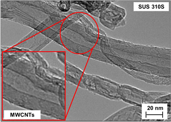
Figure 4. TEM image of growth of multi-walled CNTs on SUS 310S substrate.
Download figure:
Standard image High-resolution imageRaman spectroscopy was used to determine the types of CNT growth on the conducting substrates as well as to determine the quality of the CNTs. As shown in figure 5, there are two main features in the Raman spectra, D and G peaks [19]. The D peak is related to the breathing modes of the rings while the G peak is based on relative motion of sp2 carbon atoms. A lower IG/ID ratio of sharp D and G peaks results in aligned and ordered CNTs [31]. Kim et al [5] reported that high G-band to D-band intensity ratio (IG/ID < 5) indicates that the CNTs are of decent quality. The IG/ID ratios for SUS 310S, Inconel 600 and YEF 50 substrates were 1.18, 1.18 and 2.18, respectively. These IG/ID ratios are acceptable as compared with those of other VACNTs in the literature [32]. Therefore, the quality of the current sample is confirmed to be sufficiently high. From Raman spectral analysis, it can be concluded that 100% of the CNTs are MWCNTs, in agreement with TEM observation. There is no peak of the radial breathing mode (RBM) that reveals the presence of single-walled CNTs (SWCNTs). This result confirmed that MWCNTs could also be effectively grown on conducting substrates using the ACCVD system.
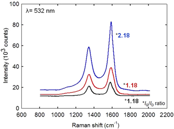
Figure 5. Raman spectra of VACNT growth collected from different substrates.
Download figure:
Standard image High-resolution imageThe formation of MWCNTs may be due to the catalytic effect of the Fe and Ni composition of the substrates. Substrates which contain a high amount of Ni and Fe tend to promote the quantity of catalytic metals which may produce MWCNTs. The growth product was still MWCNTs even when the Fe catalyst thin film was thin which produces a low yield of CNTs [33]. In addition, both SWCNTs and MWCNTs share similar remarkable properties: a high surface area per unit weight, good mechanical properties, high electrical conductivity in the metallic state and high thermal conductivity/stability. These interesting properties make CNTs very attractive for a variety of potential applications including energy storage devices [34]. By comparing the IG/ID ratios of different substrates, it can be seen that no great difference can be observed in their IG/ID ratios. This shows that, by using a similar catalyst and catalyst-support thin films, the EBPVD system will produce CNTs of high quality and quantity.
To evaluate the electrochemical performance, the VACNTs were used directly as binder-free electrodes for SCs. The shapes of the CV curves clearly indicate the existence of a nearly rectangular EDLC, as shown in figure 6. It can be seen that the graphs show a nearly rectangular profile for all substrates, which can maintained up to 1000 mV s−1 [35, 36]. The rectangular shape of the CV curves indicates more purely capacitive behaviour and low contact resistance between the CNT and substrate [37]. Lowering the contact resistance between the nanotubes and collector electrodes in EDLCs has been a major issue in developing CNT-based SCs, and is typically achieved by mixing nanotubes with conductive binders and coating collector electrodes with this composite. This process drastically modifies the electrode properties of nanotubes, leading to adverse effects on the performance of the EDLC [33, 38]. This problem does not arise in this work because the nanotubes are directly grown on the electrodes. The Csp obtained from CV curves can be calculated by the formula

where E1, E2 are the cut-off potentials in CV. i(E) is the current,  is the total voltammetric charge obtained by integration of positive (charge) and negative (discharge) sweeps in CV, (E2 − E1) is the width of the cell potential window, m is the average VACNT mass per electrode and v is the scan rate [2].

Figure 6. CV measurement of VACNTs on SUS 310S, Inconel 600 and YEF 50 supercapacitors in 6 M KOH electrolyte, at a scan rate of 1000 mV s−1.
Download figure:
Standard image High-resolution imageThe Csp values obtained at a scan rate of 1 mV s−1 for SUS 310S, Inconel 600 and YEF 50 are 33.35, 16.73 and 24.82 F g−1, respectively. It was found that Csp decreases gradually as the scan rate increases. The obtained capacitances were based on the linear dependence of capacitance on the cell potential [39]. A high Csp value indicates that the electrode material can store more energy than one with low Csp value. This is because VACNT electrodes possess a very rapid current response to the voltage shift and small equivalent serial resistance [40]. This rapid current response to the change in voltage sweep direction indicates fast ion transport to and from the CNT surface [41]. Thus, VACNT electrode on SUS 310S substrate shows high power performance to maintain at high current with high Csp (33.35 F g−1) even at 1 mV s−1 compared to other substrates which indicates that the aligned CNT array electrode has an excellent rate capability [32].
The performance of the VACNT SCs in 6 M KOH was also evaluated by CD analysis for SUS 310S, Inconel 600 and YEF 50 substrates. The Csp was calculated according to CD measurements using the formula

where I is the applied current, m is the average mass of the active material in each electrode and dV/dt is the slope of the discharge curve after the voltage (IR) drop [42].
The resulting Csp of three different substrates were 8.13 F g−1 (SUS 310S), 7.16 F g−1 (Inconel 600) and 9.69 F g−1 (YEF 50), respectively. Csp for the YEF 50 substrate is high compared with that for the other substrates. This may be due to the CNT structures having better physical contact and attachment to the substrate surfaces, resulting in higher capacitance. The high CNT-specific surface area providing contact with electrolyte ions may influence the high value of Csp for the YEF 50 substrate [43]. Moreover, the particle size of the electrode material decreases to the nano-size which means it has a relatively larger specific area and can increase the contact area with the electrolyte [44]. SUS 310S substrate still shows good capacitive performance compared with Inconel 600 substrate, which may be attributed to the well-aligned CNT structure that contacts the electrolyte ions. This type of electrical/electronic characterization also confirms the electrical conductivity of the alumina film, thus making the structures suitable for use in any kind of energy storage electrode [45].
To examine the cyclic stability and further quantify the capacitance, CD measurements were performed. As shown in figure 7, the voltage increases and decreases almost linearly with time between 0 and 1.0 V. Various constant currents were applied to observe the ability of the electrodes to work from lower to higher current. The black, red, blue and green lines correspond to applied currents of 0.05, 0.10, 0.50 and 1.00 mA, respectively, for all substrates. The Csp decreased with increasing current for all substrates. The discharge times at 0.05 mA of each cycle for SUS 310S, Inconel 600 and YEF 50 were 35.6 s (13.29 F g−1), 49.9 s (21.88 F g−1) and 54.2 s (26.57 F g−1) respectively. The YEF 50 substrate shows the highest Csp value compared with SUS 310S and Inconel 600 substrates. As shown in figures 7(a)–(c) the discharge times of the VACNT electrode on the different conducting substrates were nearly the same. The very rapid CD (in seconds) for all substrates is advantageous for SC applications [46]. Moreover, a dynamic long lifetime of the electrode materials can be expected from pure aligned CNTs that were produced using the ACCVD technique [47]. For SC applications using a CNT-based electrode, the ability to accumulate charge in the electrode–electrolyte interface strongly depends on the accessibility of the nanotubes to ions. Therefore, it can be suggested that the morphological structure of aligned CNTs might influence the performance of SCs, with the accessibility of ions to aligned CNTs better than that for entangled CNTs [48].

Figure 7. Discharge time at different currents for (a) SUS 310S, (b) Inconel 600, and (c) YEF 50 substrates.
Download figure:
Standard image High-resolution imageThe VACNT electrode was further tested by CD for 1000 cycles in 6 M KOH electrolyte with a current of 0.5 mA in order to evaluate its performance over its lifecycle. After 1000 cycles, only a slight decrease in Csp can be observed. The electrode exhibited almost lossless performance in specific capacitance after 1000 cycles; the slight decrease in Csp indicates excellent stability of the aligned CNT array electrode, as shown in figure 8. High retention of Csp was observed in as-grown VACNT SCs. SUS 310S, Inconel 600 and YEF 50 retained 96.1%, 100.0% and 97.4%, respectively, of the original value of Csp. This finding indicates excellent capacity retention and better long-term cycling stability of the VACNT electrode. Moreover, after 1000 cycles, the Co/Al2O3 on all substrates was still strongly adhered to the CNTs [49]. Such high retention indicates the stability of this material and its structure as a result of fast electrolyte ion and electron transport, and is clearly very good for EDLC [50].

Figure 8. The capacitance retention analysis for VACNTs on SUS 310S, Inconel 600 and YEF 50 supercapacitors measured up to 1000 cycles at a fixed current of 0.5 mA.
Download figure:
Standard image High-resolution image
4. Conclusions
After the deposition of Al2O3 and Co ultra-thin films, VACNTs were successfully grown on different Fe–Ni based metal alloy foils at 700 °C using the ACCVD technique. The CVD process resulted in similar morphological structures and good CNT distribution on all substrates, and their structures (dimension, walls) have been confirmed by means of FESEM, TEM and Raman spectroscopy. From electrochemical analyses, the CV curve shows a nearly rectangular shape up to scan rates of 1000 mV s−1. It can be concluded that the aligned CNT structure produces better electrochemical performance because it allows fast ion transportation. The capacitance retention measurement for 1000 cycles proved that all substrates still had strong adhesion to the CNTs, indicating the stability of this material for EDLC applications. The performance of SCs depends on several conditions, including electrolyte and electrode material. Thus, by replacing the aqueous electrolyte with wider potential range of electrolytes, such as ionic liquids and organic electrolytes, higher SC performance may be achieved. It is necessary to use a glove-box to control the moisture and oxygen contents.
Acknowledgments
Authors are grateful to Universiti Teknikal Malaysia Melaka for UTeM Zamalah Scheme financial support, and Ministry of Higher Education for Exploratory Research Grant Scheme no. ERGS/1/2013/TK04/UTEM/02/01/E00031. Also, special thanks to the Japan Advanced Institute of Science and Technology, Japan for technical support in x-ray photoelectron spectroscopy analysis under the student's mobility programme between JAIST–UTeM.