

Abstract
PANI/MWCNT-ZnS nanocomposites with different contents of ZnS wt.% have been synthesized by the chemical oxidative in situ polymerization reaction of aniline in the presence of multi-walled carbon nanotube (MWCNT). TEM, XRD, RAMAN and TGA studies have been done for the structural and thermal characterizations of the samples. The particle sizes of ZnS nanoparticles have the values in the range from 3.21 to 5.08 nm. XRD spectrum reveals the co-existence of MWCNT, ZnS in PANI matrix, where ZnS forms a hexagonal structure. TGA result shows that nanocomposite becomes more thermally stable with increase in ZnS content. The dc electrical transport property of PANI/MWCNT-ZnS nanocomposites has been investigated within a temperature range 77 K ⩽ T ⩽ 300 K. The dc conductivity follows a 3D variable range hopping (VRH) model. A large magnetoconductivity change (23.1%) is observed for 2 wt.% ZnS content in PANI/MWCNT-ZnS, which is explained by the wave function shrinkage model.
Export citation and abstract BibTeX RIS

Original content from this work may be used under the terms of the Creative Commons Attribution 3.0 licence. Any further distribution of this work must maintain attribution to the author(s) and the title of the work, journal citation and DOI.
1. Introduction
In recent years, polyaniline (PANI) has occupied an important place in the family of conducting polymers due to its good stability in air, simplicity in doping, improved electronic properties and high conductivity in the doped state [1]. Studies on nanoparticles dispersed within a polymer matrix is intriguing since these materials offer tremendous options for combining properties stemming from both the inorganic components and the polymers [2–4]. The polymer matrix provides additional qualities such as processibility, solubility or the thermal stability of the systems. A variety of preparative methods is available for obtaining nanoparticles within a polymer matrix. Most of them are based on in situ reactions; that is, the particles are generated from the respective precursors in the presence of the matrix polymer. Their relative large conductivity, flexibility, low cost and light weight make conducting polymers much more desirable than metals in many applications [5]. Zinc sulfide (ZnS) is the most studied and widely used II–VI class inorganic compound semiconductor due to its applications as fluorescent material and in photonic research [6, 7]. ZnS has been synthesized as quantum dots, nanowires, nanobelts and nanocombs [8]. In recent years carbon nanotubes (CNTs) have been intensively studied due to their unique structure-dependent mechanical, chemical and electronic properties [9, 10]. However CNTs/polymer nanocomposites have drawn a great attention due to the tremendous enhancement in their electrical, thermal, optical, and structural properties [11–13]. Large aspect ratios of CNTs can enhance the electrical conductivity of polymer composite [14]. However, it is very difficult for the uniform dispersion of CNTs in a polymer matrix because they have very large surface areas and strong van der Waals force, which result in aggregation [15]. Bompilwar et al [16] studied the thermal stability of CdS/ZnS nanoparticles embedded in polyaniline, and reported that the particle size is about 10 nm and the nanocomposites are more thermally stable than that of pure polyaniline. Yao et al [17] observed that the electrical conductivity of the 41.4 wt.% SWNT sample reaches 1.25 × 10⁴ S m−1, which is more than 1 order of magnitude larger than the pure PANI. Kim et al [18] have also reported the dc conductivity of polystyrene/MWCNT nanocomposite with different wt% of MWCNT in polymer matrix and they reported that the order of conductivity range lies between 10−10 to 10−4 S cm−1. Shrivastava et al [19] studied the electrical percolation and conductivity within the temperature range 20–80 °C of high-impact polystyrene/MWCNT nanocomposites. Among them, silver-decorated CNTs (Ag-CNTs) have gained extensive attention due to their potential applications as catalyst, optical limiters and advanced materials [20, 21]. Mondal et al [22] synthesized MWCNT-CdS nanostructures embedded in polyvinyl alcohol (PVA) matrix at room temperature. The particle size is about 10 nm. The high dielectric property and charge storage behavior of this composite structure are studied. The ac and dc conduction mechanisms of such high dielectric material are explained using impedance spectroscopy.
The nature of the interactions between the polymer-nanoparticles and polymer- CNTs can be varied by electrostatic and van der Waals interactions and hydrogen bonding [23]. Thus, the dispersion of MWCNT and ZnS into polyaniline (PANI) matrix is much more difficult. The magnetoconductivity of this kind of composite is still unclear. Here we have developed an effective technique for the synthesis of MWCNT-ZnS nanostructure embedded in PANI matrix and achieved large negative magnetoconductivity (changes upto 23.1%) at room temperature which is explained by wave function shrinkage model. Detailed electrical transport property is studied. This composite has much advantage for electromagnetic shielding application and electronic industry.
2. Experimental
Aniline monomer (C6H5NH2, ⩾99%), zinc acetate dihydrate (Zn(CH3COO)2.2H2O, ⩾99.9%), sodium sulfide (Na2S), cetyltrimethyl ammonium bromide [C19H42NBr] (CTAB), ammonium peroxodisulfate (APS) [(NH4)2S2O8], glacial acetic acid (CH3COOH, ⩾99%), and ultrapure water (milli Q, resistivity >18.2 MΩ cm) were used for materials synthesis. Nitric acid (HNO3, 70%), hydrochloric acid (HCl, 30%), acetone, and ethanol were purchased from Merck, India and purified as required for the investigation.
At first we take concentrated HNO3 and concentrated HCl (1:3 in volumes) solution and mix with MWCNTs (Carbon Inc.) and sonicated 12 h for purification. Then, the solution was washed with ultrapure water for neutralization and dried in a vacuum at ~80 °C. For functionalization, 1 mg of purified MWCNTs and 2 g of CTAB were mixed with 50 ml of ultrapure water under continuous stirring for 8 h and dried at 80 °C. PANI/MWCNT-ZnS composite was prepared via in situ polymerization as follows. The desirable amount of Zn(CH3COO)2.2H2O was mixed with 30 ml ultrapure water (named as, mixture-I) and 0.5 g Na2S was mixed with 15 ml ultrapure water (named as mixture-II). 3 g of APS was mixed with 50 ml of ultrapure water (named as mixture-III) and kept it in refrigerator for cooling to achieve 5 °C. First, mixture-II was added dropwise in the mixture-I under stirring. Concurrently, in this solution, 2 ml of double distilled aniline monomer, 2 ml acetic acid and 1 mg of functionalized MWCNTs were added under vigorous stirring in an ice bath. Ice cooled APS solution (mixture -III) was then added to the above solution. A green colored solution was obtained after 4 h stirring. After that the solution was kept in refrigerator at rest for 24 h to complete the in situ polymerization process of aniline to polyaniline and it was centrifuged at 10 000 rpm and washed several times with ethanol and water to remove monomer, oligomer, and excess of oxidant. Two nanocomposites containing different desired amounts of Zn2+, namely 1 wt% and 2 wt%, were investigated. They are denoted PANI/MWCNT-ZnS-1 and PANI/MWCNT-ZnS-2. For the comparison we investigated also one sample without MWCNT and Zn2+ (i.e. pure PANI). Samples are marked as S0, S1, S2, where S0, S1, S2 indicates pure polyaniline and PANI/MWCNT containing 1 and 2 wt.% of Zn2+, respectively.
The structure of nanocomposites and particles sizes of ZnS nanoparticles were examined using a high-resolution transmission electron microscope (HR-TEM) (JEM-3100, JEOL, Japan attached with an energy dispersive x-ray analysis (EDX) facility, INCA, Oxford, UK) operated at an accelerating voltage of 300 kV. The phase identification of the samples were done using X 'Pert pro x-ray diffractometer with nickel filter Cu-Kα radiation (λ = 1.5414 Å) in 2θ range from 20 to 70°. Thermogravimetric analyses (TGA) of the samples were carried out on STA 6000 PerkinElmer TGA instrument at a heating rate of 10 °C per minute in N2 atmosphere over a temperature range of 50–700 °C. The nanocomposities were characterized by a Raman spectroscope (inVia Reflex, Renishaw, Gluocestershire, UK) at room temperature. All spectra were excited by the 532 nm line of a diode-pumped solid state laser (Spectra Physics, San Jose, CA) in the backscattering configuration with a charge-coupled device detector. The spectral resolution of the instrument was about 0.1 cm−1. DC resistivity of the samples was measured by Keithley 6514 electrometer. The magnetoconductivity is measured by varying the transverse magnetic field (B ⩽ 1 T) using an electromagnet (EM-250).
3. Results and discussion
A comparison of the XRD spectra of different wt.% of Zn2+ contents in PANI/MWCNT-ZnS nanocomposites (S1 and S2) and pure PANI (S0) are shown in figure 1. The x-ray pattern of the pure PANI displays the presence of a broad peak at ~25.28° assigned to (2 0 0). This peak in PANI may arise due to regular repetition of monomer unit of aniline. The XRD pattern of nanocomposite shows the characteristic peaks which represent Bragg's reflections from (1 1 1), (2 2 0), (3 1 1) planes of the hexagonal phase (JCPDS no-00-005-0492) of ZnS. These peaks in XRD study of nanocomposites confirm that ZnS is present in the PANI matrix. It is to be noted that (1 1 1) peak of ZnS in nanocomposite is the combination of (2 0 0) peak of PANI and (0 0 2) peak of MWCNT. It confirms the co-existence of MWCNT and ZnS in PANI matrices. The intensities of these diffraction peaks gradually increase with increasing ZnS content, indicating that the ZnS particles have been successfully incorporated into the bulk polymer matrices.
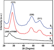
Figure 1. XRD pattern of PANI and different content of ZnS in nanocomposites of PANI/MWCNT-ZnS (S1 and S2).
Download figure:
Standard image High-resolution imageThe structure of composites and the dispersion of MWCNTs and ZnS particles in the composites are examined by high-resolution TEM. TEM images of composites (figure 2) clearly show the distribution of ZnS particles over MWCNT surfaces in the polymer matrix. This indicates the formation of a solid hetero-network composed of PANI, MWCNTs and ZnS particles. Also, there are aggregations of bundles of MWCNTs or ZnS due to either the van der Waals interaction between MWCNTs or electrostatic interactions between ZnS particles, respectively [24, 25]. However, a significant change over particle size is observed (upper inset in figures 2(a) and (b)) due to increase in Zn+ content in the composites. The average particle size of ZnS is about 3.21 nm for 1wt.% Zn2+ and 5.08 nm for 2wt.% Zn2+ content in the composites, respectively. For qualitative elemental analysis of the prepared nanocomposites, EDX spectroscopy (figures 3(a) and (b)) was applied. It shows the presence of Zn and S in the composite (figure 3). The stoichiometry of the obtained powder according to the EDX wt.% and atomic % are tabulated inside figures 3(a) and (b) for 1 wt.% Zn2+ and 2 wt.% Zn2+, respectively. In this spectrum, peaks from O and C elements also appeared. We consider that O is due to oxidation of polyaniline and from functionalized MWCNTs, and C element is obtained from both of MWCNTs and polymer unit.
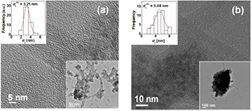
Figure 2. HRTEM micrograph of the PANI/MWCNT-ZnS nanocomposite with ZnS content of (a) 1 wt.% and (b) 2 wt.%.
Download figure:
Standard image High-resolution image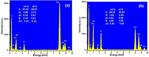
Figure 3. Typical EDX spectra of PANI/MWCNT-ZnS nanocomposite with ZnS content (a) 1 wt.% and (b) 2 wt.%.
Download figure:
Standard image High-resolution imageRaman spectroscopy is a powerful and non-destructive procedure sensitive to local environment. This technique is ideal for analyzing homogenous dispersion of semiconducting nanoparticles in the polymer matrix as well in MWCNT. Here, we compare the Raman spectrum of individual components such as PANI, MWCNTs, and ZnS with PANI/MWCNT-ZnS composites which is shown in figure 4. The Raman spectrum of pure PANI (without MWCNT and ZnS) shows the typical bands at ~1360 cm−1 and 1570 cm−1 corresponding to C–C and C=C stretching mode in the quinoid rings respectively [26, 27]. The spectrum of pure MWCNTs (without PANI and ZnS) exhibits three usual bands—the D-peak at ~1350 cm−1 due to amorphous carbon and defects induced line, the G-peak at ~1580 cm−1 due to in-plane stretching of E2g mode and the 2D-peak at ~2680 cm−1 due to double tone of D [28]. The Raman spectrum of ZnS particles shows prominent three bands at ~221 cm−1, ~312 cm−1 and ~348 cm−1 corresponding to longitudinal optical (LO) phonon modes of first order (1 − LO), surface optical (SO) phonon modes of first order (1 − SO), and E1(LO), respectively. These three bands strongly indicate the high quality of ZnS quantum dots [29, 30]. A clear enhancement of intensity of the existing peaks related to PANI and MWCNT in the composites samples along with 1 − LO, 1 − SO and E1(LO) peak of ZnS particles were observed in figure 4. Therefore, the synergistic effect in Raman band of the composite samples gives a confirmational evidence of dispersion of ZnS, CNT in the host polymer matrix and their interaction between them.
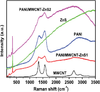
Figure 4. Raman spectra of each component and their composites.
Download figure:
Standard image High-resolution imageTGA measurement of polyaniline (S0) and PANI/MWCNT-ZnS nanocomposite (S1 and S2) was done in the temperature range 50 °C–700 °C and the thermograms are presented in figure 5. Thermogram of pure polyaniline shows that the mass loss began around 50 °C, and about 17% weight loss occurred upto 150 °C. A very little of amount of mass loss was observed upto about 250 °C and then rapid mass loss occurred till 600 °C. The initial mass loss was due to the loss of water molecules, the nearest mass loss may be attributed to the loss of oligomers and the subsequent rapid mass loss occurred due to the degradation of the polymer chain. On the other hand, in case of nanocomposite rate of loss of mass started from 218 °C and continued upto 348 °C. So this mass loss is very small in comparison to the mass of polyaniline. This thermogravimetric analysis indicates better thermal stability of the composite than that of pure polyaniline. The better thermal stability of polyaniline composite could be explained by the dominancy of the benzenoid structure. Alternatively, the inferior thermal stability of pure undoped polyaniline was due to the presence of a quinoid ring in its structure [31].
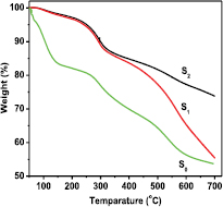
Figure 5. TGA spectrum of PANI and different content of ZnS in nanocomposites of PANI/MWCNT-ZnS (S1), and (S2).
Download figure:
Standard image High-resolution imageIn order to demonstrate the electronic transport mechanism of PANI/MWCNT-ZnS composites, the dc resistivity of the samples is measured within a temperature range 77 K ⩽ T ⩽ 300 K. The room temperature conductivity of the investigated samples in absence of magnetic field is summerised in table 1. It is observed that the introduction of ZnS in PANI/MWCNT significantly increases the conductivity of the samples. The presence of ZnS in PANI/MWCNT forms the conducting islands between the insulating matrices, which will be enlarged with increase of ZnS in PANI/MWCNT matrix. As a result the conductivity of the composite may enhance. Figure 6 shows the temperature dependence of the resistivity ρ(T) in the absence of the magnetic field. It is observed that the resistivity of the samples decreases with increasing the temperature which indicates the semiconducting nature of the samples. The temperature dependence of resistivity can be well described by the Mott variable range hopping (VRH) model. According to this model, the temperature variation of resistivity can be expressed as

where the VRH exponent γ determines the dimensionality of the conducting medium by the relation  . For three, two and 1D systems, the possible values of γ are 1/4, 1/3 and 1/2, respectively. ρ(0) is the resistivity at infinite temperature, TMott is the Mott characteristic temperature which depends on the electronic structure and the energy distribution of the localized states. TMott can be written as
where kB is the Boltzmann constant, N(EF) is the density of states at the Fermi level and Lloc is the localization length. A variation of lnρ(T) with T−1/4 has been plotted in figure 6 for all the samples. The figure shows two different slopes for different samples for the investigated temperature range 77 K ⩽ T ⩽ 300 K. Hence the experimental conductivity has been well described by equation (1) with VRH exponent γ = 1/4. Thus, a three dimensional (3D) charge transport mechanism is suitable for explaining the temperature dependence of dc resistivity of the investigated samples. TMott of the samples for different temperature range can be calculated from the slope of the curves of figure 6, and is enlisted in table 1. It is observed that the value of TMott decreases by inclusion of MWCNT with 1% of ZnS and then also increases with further increase of ZnS content. It is also observed that the TMott values at higher temperature are greater than the values at lower temperature. This anomalous behavior may be due to the strong interaction with the polymer and MWCNT at higher temperature than lower temperature. The conducting islands due to ZnS are present in between the insulating PANI/MWCNT matrix; the electronic wave functions extend in three-dimension. As a result, 3D hopping of electrons occurs in the investigated samples. We can observe two different slopes from the study of activation behavior of the PANI/MWCNT-ZnS nanocomposites (figure 7). The activation energy of all the samples can be calculated by the Arrhenius equation:

where  is the resistivity at infinite temperature and Ea is the activation energy. The activation energy in the two different temperature regions is enlisted in table 1. The activation energy at higher temperature is greater than the values at lower temperature. This suggests that at higher temperature range the interaction between MWCNT and polymer is stronger than the lower temperature range. However, the presence of ZnS may influence the interaction due to which the activation energy again decreases with increasing ZnS.
Table 1. Different electrical parameters of nanocomposites.
| Parameters | Samples | ||
|---|---|---|---|
| S0 | S1 | S2 | |
| σ(300 K) (Ω−1 m−1) | 7.85 × 10⁻² | 10.7 × 10⁻¹ | 21.93 × 10⁻¹ |
| Ea (meV) at low T range | 2.05 | 1.10 | 1.30 |
| Ea (meV) at high T range | 9.52 | 7.03 | 9.30 |
| TMott (K) at low T range | 72.3 | 6.9 | 8.3 |
| TMott (K) at high T range | 5725 | 1050 | 2212 |
| Δσ(B)/σ(0)% (at 300 K) | −0.25% | −9.4% | −23.1% |
| Lloc (nm) (at 300 K) | 22 | 25 | 18 |
| Rhopp (nm) (at 300 K) | 16.17 | 14.16 | 9.44 |
| N(EF) (J−1 cm−3) (at 300 K) | 2.45 × 1037 | 4.74 × 1037 | 1.73 × 1038 |
| WH (meV) | 34.2 | 29.6 | 28.4 |
| WP (meV) | 89.3 | 80.2 | 78.0 |
| J (meV) | 10.45 | 10.50 | 10.60 |
Note: Conductivity at temperature 300 K (σ(300 K)), activation energy (Ea), Mott characteristic temperature (TMott), % change of magnetoconductivity (Δσ(B)/σ(0)) at temperature 300 K and B = 0.8 T; localization length (Lloc); hopping length (Rhopp) and the density of states (N(EF)) of states at Fermi level. Other electrical parameters: the hopping energy (WH), the polaron binding energy (WP) and the electronic orbital overlap integral (J).
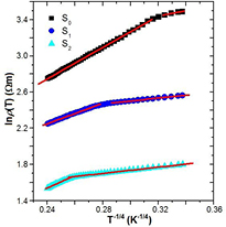
Figure 6. Variation of the resistivity ρ(T) with T−1/4 of PANI and different content of ZnS in nanocomposites of PANI/MWCNT-ZnS (S1 and S2). The solid lines are fitted to equation (1).
Download figure:
Standard image High-resolution image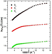
Figure 7. Variation in the dc resistivity with 1000/T of PANI and different content of ZnS in nanocomposites of PANI/MWCNT-ZnS (S1 and S2). The solid lines are fitted to equation (3).
Download figure:
Standard image High-resolution imageDue to strong particle lattice interaction quasiparticle polaron formed by the carrier and lattice distortion. When the interaction is limited within a small unit cell, the small polaron model is applicable at high temperature. Hence two different conduction mechanisms like adiabatic and nonadiabatic polaron hopping are responsible to analyze the experimental conductivity data. According to adiabatic small polaron model (Emin–Holstein model) [32] the temperature dependent conductivity is given by

where n is the polaron density, e is the electronic charge, a is the hopping distance,  is the frequency of optical phonon,
  is the Boltzmann constant and
  is the hopping energy. The temperature dependence dc conductivity (ln[Tσdc(T)] versus 1/T) for MWCNT-ZnS doped PANI composite is shown in figure 8(a) at temperature range 200–300 K. From the linear variation we calculate the hopping energy for different samples are shown in table 1. According to nonadiabatic small polaron model (Holstein model) [33], carriers are not able to follow rapid fluctuation of lattice for long time, the corresponding conductivity can be expressed as

where WP is the polaron binding energy, J is the electronic orbital overlap integral and  with h is the Planck's constant. From the variation of ln[T3/2σdc(T)] versus 1/T shown in figure 8(b) we find straight line variation. From the value of slope and intersect of the fitted straight line we calculate the value of WP and then J (with
  ), shown in table 1. To understand the hopping conduction mechanism for the studied samples, it is important to do the detailed analysis of the samples using following relation

Figure 8. Fits to high temperature conductivity measurement using (a) adiabatic and (b) nonadiabatic small polaron models of PANI and different content of ZnS in nanocomposites of PANI/MWCNT- ZnS (S1 and S2).
Download figure:
Standard image High-resolution imageUsing above equation we calculate Jmax at various temperatures lies between Jmax (200 K) = 194.8 meV to Jmax(300 K) = 216.5 meV for S0, S1 and S2 samples. Since the value of Jmax is higher than J, based on Holstein model, nonadiabatic small polaron model is applicable for these samples and J can be treated as a perturbation in the corresponding Schrödinger equation [34].
The influence of magnetic field in the conductivity of the composites is studied by measuring the magnetoconductivity in presence of magnetic field up to 0.8 T at a constant temperature. Figure 9(a) shows the variation of magnetoconductivity ratio [σ(B)/σ(0)] with magnetic field at room temperature of different samples. It is observed from the figure that the magnetoconductivity is negative and increases with increasing ZnS content in PANI/MWCNT and is listed in table 1. It is observed from the table that the change of magnetoconductivity at room temperature increases with increasing ZnS in PANI/MWCNT matrix from −9.4 to −23.1%. However, with the increase in ZnS content, which is an donor-type (n-type) semiconductor, the conducting island between the insulating matrices increases which results in the decrease in average localization length of the composite and thus the magnetoconductivity becomes more negative. Hence, we can observe large negative magnetoconductivity in S2 sample which is few times larger than previously reported value for PVA-MWCNT composite [35]. In the hopping processes, the magnetoconductivity data can be analyzed by two mechanisms like (i) wave function shrinkage model [36, 37] and (ii) forward interference model [38–40]. The wave function shrinkage model is presented by the contraction of the wave function of the electrons in the presence of magnetic field, which results in a reduction in average hopping length and hence negative magnetoconductivity has been observed, i.e. conductivity decreases with increasing magnetic field. However, in the forward interference model the observed magnetoconductivity is positive. As the measured magnetoconductivity for the all investigated samples are negative, we may presume that the contribution due to wave function shrinkage model is dominating over the forward interference model. So we can analyze our experimental data by using wave function shrinkage model. According to wave function shrinkage model under a small magnetic field, the magnetoconductivity ratio can be written as [37]

where t1 = 5/2016 and Lloc is the localization length. The variation of ln[σ(B)/σ(0)] with B2 is linear for different samples which are shown in figure 9(b). According to figure the samples S0, S1 and S2 show single slope throughout the investigated field region. The points represent the experimental data and the lines represent the theoretical best fit in accordance with the wave function shrinkage model. From figure 9(b) it is evident that the experimental data can be well described by the theory indicated by equation (7).
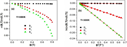
Figure 9. (a) The variation in dc magnetoconductivity with perpendicular magnetic field of PANI and different content of ZnS in nanocomposites of PANI/MWCNT-ZnS (S1 and S2) at 300 K; (b). The variation of ln[σ(B)/σ(0)] with B2 of PANI and different content of ZnS in nanocomposites of PANI/MWCNT-ZnS (S1 and S2) at 300 K. The solid lines are fitted to equation (8).
Download figure:
Standard image High-resolution imageFrom the slopes of the graph, the localization length has been calculated, which is decreased with increase of ZnS content in the PANI/MWCNT composites and is indicated in table 1. The average hopping length for different samples has been calculated using the relation:

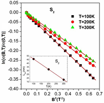
The values of Rhopp decreases with increasing of ZnS content in the various PANI/MWCNT composites and listed in table 1. Figure 10 shows the variation in magnetoconductivity of the sample S2 at different temperature with varying magnetic fields. As the temperature increases, the magnitude of the magnetoconductivity decreases. This is may be due to the decrease of localization length with increasing temperature which is shown in inset of figure 10.
Figure 10. The variation of ln[σ(B)/σ(0)] with B2 of the sample S2 at different temperature. The solid lines are fitted to equation (8). Inset shows the variation of localization length with different temperature of the sample S2.
Download figure:
Standard image High-resolution image
4. Conclusions
PANI/MWCNT-ZnS composites have been synthesized by an in situ chemical oxidative polymerization reaction and their morphology, structure, thermal stability and low temperature conductivity were investigated. TEM images confirmed that in all PANI/MWCNT-ZnS samples ZnS are distributed over the MWCNT. The formation of hybrid materials is confirmed by the XRD analysis. X-ray peaks of composites confirm the superimposition of the peaks of CNT, ZnS and PANI. Thermogravimetric analysis gives evidence for better thermal stability of different PANI/MWCNT-ZnS composites than PANI itself. Electrical transport properties of the investigated samples were measured within temperature range 77 K ⩽ T ⩽ 300 K in presence of transverse magnetic field up to 1 T as well as without magnetic field. Incorporation of ZnS in polymer matrix increases the conductivity and magnetoconductivity. All the composite samples have two activation processes; one is due to dominant charge transfer process by PANI at lower temperature and the other is due to PANI/MWCNT-ZnS composites at higher temperatures. Negative magnetoconductivity was observed in PANI and PANI/MWCNT-ZnS composites which can be explained by the wave function shrinkage model. Incorporation of ZnS in PANI/MWCNT matrix enhances the magnetoconductivity by 23.1% at room temperature. Thus, our synthesized PANI/MWCNT-ZnS composite would be a potential candidate for electronic industries in near future.
Acknowledgments
The authors are thankful to CSIR, Govt. of India (Project no. 03/1278/13/EMR-II) for funding.