
Abstract
We propose the passive and active control of a plasmonic mimic of electromagnetically induced transparency in stereometamaterials and planar metamaterials, respectively. We show that the magnetic plasmon resonance (MPR) plays an important role in the coupling of bright and dark modes and its mechanism is discussed. This study provides approaches and guidelines to make use of MPR for the realization of plasmonic switching.
Export citation and abstract BibTeX RIS

Content from this work may be used under the terms of the Creative Commons Attribution-NonCommercial-ShareAlike 3.0 licence. Any further distribution of this work must maintain attribution to the author(s) and the title of the work, journal citation and DOI.
1. Introduction
When sodium gas is chilled down to nanokelvin temperatures, a Bose–Einstein condensate is formed, which is a dense cloud of atoms all in the same quantum state. In general, most of the light is absorbed if it traverses the dense gas near any one of its resonances (i.e. spectral lines) [1]. However, this absorption can be circumvented by a technique called electromagnetically induced transparency (EIT). At first, all of the atoms are put into the ground state |1〉 using a magnetic filter. Then a second laser beam, called a coupling beam, illuminates the gas, at a frequency equal to the transition energy between a nearby unpopulated hyperfine ground-state level | 2 〉 and the excited state | 3 〉. As a result of coupling of the two ground states, a destructive quantum interference effect takes place between the two alternative pathways of |1〉–|3〉 and |1〉–|3〉–|2〉–|3〉, where the former and the latter are the direct and the indirect pathways, respectively. Therefore, there is no possibility of excitation to | 3 〉 and subsequent spontaneous emission. When the probe beam illuminates the gas, the otherwise opaque medium becomes transparent [2].
Recently, EIT has been mimicked in a variety of classical linear systems [3], such as a mechanical oscillator, RLC circuits [4], optical resonators [5–8], optical antennas [9–15], trapped-mode patterns [16–18], split-ring resonators [19–22] and waveguide-coupled resonators [23–25]. As an EIT-like scheme at optical frequencies, optical antennas [26, 27] with subwavelength features are good candidates, where the half-wavelength scaling breaks down owing to the role of surface plasmon polaritons (SPPs) [28]. In the prototype of plasmon-induced transparency, the unit cell generally consists of the optical dipole and quadrupole antennas. The former is a single metal strip, and the latter is a pair of metal strips, the excited plasmonic modes of which are termed the 'bright' and the 'dark' modes, respectively, depending on how strong an incident light from free space can be coupled into the plasmonic modes [29, 30].
In general, the EIT-like effect is attributed to the coupling of the bright and dark modes, and the coupling strength depends on the spatial separation of two modes in planar metamaterials [9] as well as stereometamaterials [10, 31]. However, what the essence of the coupling is and how the coupling takes place are still mysterious. In this work, the underlying physics of plasmon-induced transparency is discussed, which is crucial not only to understand the mechanism but also to utilize for the manipulation of SPPs and the development of novel properties.
2. Prototype of plasmonic EIT system
In the prototype of plasmonic EIT, the unit cell, in general, is composed of a bright and a dark element, where the bright element is a single metal strip and the dark element is a pair of metal strips. The combination of the bright and the dark elements is either horizontal or vertical, as shown in figure 1. The permittivity of metal, ε m , is described by the Drude formula, ε m =1−ω p 2/[ω (ω+iγ)], where ω p and γ are the plasmon frequency and the scattering frequency, respectively. The numerical simulation is performed using a finite-integration package, CST Microwave Studio.
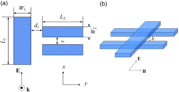
Figure 1 Schematic of a typical unit cell consisting of a bright element (single metal strip) and a dark element (a pair of metal strips) in the form of (a) horizontal and (b) vertical combinations. They are termed as the planar metamaterial and the stereometamaterial, respectively.
3. Passive and active control of plasmonic EIT
The control of SPPs is of great importance not only for the basic design of devices but also for the manipulation of properties. We start with the metamaterial in [10], where the bright and the dark elements are stacked vertically with a lateral displacement. The displacement plays a dominant role in plasmonic EIT, since, in the case of symmetry, the zero displacement results in the disappearance of the feature. The plasmon-induced transparency totally fades away and only a high reflectance is observed. Therefore, most researchers have concluded that the asymmetry is a prerequisite [10, 21, 32]. Nevertheless, Jin et al [13] found that it is true only for the fundamental plasmonic modes. As far as the higher-order modes are concerned, the asymmetry is not always necessary, where the symmetric structure also provides the feature of plasmonic EIT.
For instance, the unit cell, as shown in figure 1(b), is used as the building blocks without the lateral displacement. Lu et al [33] proposed that the coupling in plasmonic EIT stems from the excitation of magnetic plasmon resonance (MPR). Therefore, according to this physical picture, if the higher-order MPR can be excited in the pair of strips, it is possible to obtain the plasmonic EIT even in the symmetric structures. We use a structure that is the same as that in [10], except for two major differences. One difference is that the dielectric spacer and the substrate are not taken into account for simplicity. They are treated as air without any loss of generality. The other difference is that the pair of strips is elongated to 790 nm, about twice the length of the strips in [10]. This is the only trick that we use for the establishment of plasmonic EIT even in symmetric structures. The reason for the elongation is that the second-order MPR could be excited such that it overlaps the resonant frequency of the bright element to form the coupling. When the pair is coupled with the single strip, the otherwise suppressed transmission in symmetric structure appears, as illustrated in figure 2. The black curve is plotted for a short length of 315 nm for comparison and the other curves correspond to a length of 790 nm.
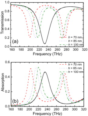
Figure 2 (a) Transmission and (b) absorption spectra with fixed L2 =790 nm and various vertical distances h. The black curve is plotted for reference, where L2 =315 nm. The other geometric parameters are W1 =W2 =80 nm, s=100 nm, L1 =346 nm and the thickness of each strip is 40 nm. The metal is modeled as gold with a plasmon frequency of ω p =2π×2.175×1015 rad s −1 and a scattering frequency of 1.225×10¹⁴ Hz [10, 34, 35].
It is found that the plasmonic coupling is reconstructed based on the excitation of the second-order MPR by elongating the pair of strips. This explicitly illustrates the possibility of passive manipulation of plasmonic EIT. However, it has difficulty in changing the geometrical size of elements after fabrication. Therefore, active control is demanded for plasmonic devices, where the response could be altered dynamically.
Based on the structure in figure 1(a), we modify it to be symmetric (i.e. add one more bright element on the right side), as shown in the right inset of figure 3. As discussed above, the symmetry gives rise to the disappearance of plasmonic EIT without considering the higher-order modes. Nevertheless, as far as the whole structure is concerned, the symmetry of incident light must be taken into account as well as the unit cell. It is expected that the asymmetry can be introduced at oblique incidence without altering the unit cell.

Figure 3 (a) Angular-dependent transmission spectra from 0 to 10° with an increment of 2° in the yz plane, as shown in the right inset. The spectral region of the transmission is zoomed in, as shown in the left inset. The geometric parameters are W1 =50 nm, L1 =124 nm, W2 =30 nm, L2 =114 nm, s=80 nm and d c =18 nm, and the thickness of each strip is 20 nm. The metal is modeled as silver with a plasmon frequency of ω p =1.366×10¹⁶ rad s −1 and a scattering frequency of 3.07×10¹³ Hz [36, 37].
Figure 3 shows the evolution of the transmission spectra when the incident beam is varied from normal to oblique (0 to 10°). It is found that no light can traverse at normal incidence. It can be explained that the magnetic field of the bright mode on the left has the same amplitude and the opposite direction with respect to that on the right such that the opposite circular currents are generated by the two bright elements and cancel each other out. As a result, MPR is suppressed and the coupling vanishes. When the incident angle increases, the transmission is gradually recovered. It is ascribed to the imbalance of the magnetic fields from both wings, arising from the vertical magnetic component of the incident beam.
4. Conclusions
We have proposed the passive and the active control of plasmonic EIT in the stereometamaterials and the planar metamaterials, respectively. The crux of plasmonic EIT is whether MPR is excited, which can be the higher-order modes as well as the fundamental modes. Furthermore, we show that the symmetry should be considered with respect to not only the unit cell itself but also the whole structure, including the incident beam. Based on this, the transition of symmetry to asymmetry can be realized by adjusting the incident angle of light.
Acknowledgment
This work was supported by MEST/NRF through the Quantum Photonic Science Research Center, Korea.