
Abstract
The work presented here concerns the development of optoelectronic oscillators. Their high spectral purity is one of their most interesting qualities for photonics signal processing, communication or radio over fiber systems. The classical structure is based on a very long optical fiber loop acting as a delay line. Different techniques have been introduced, such as multiple loops, in order to get very narrow spectral lines and large mode spacing. Among the problems due to long fiber loops, there is the size and the requirement of temperature control. In order to go toward integrated solutions, it is also possible to introduce optical resonators instead of the delay line. Such resonators should present a very high quality factor in order to keep a low phase noise. Different solutions based on silica microspheres, on polymer materials or on silicon can be investigated. These resonators can be directly implemented with the associated Mach–Zehnder optical modulators in the case of both polymer and silicon materials.
Export citation and abstract BibTeX RIS

Content from this work may be used under the terms of the Creative Commons Attribution-NonCommercial-ShareAlike 3.0 licence. Any further distribution of this work must maintain attribution to the author(s) and the title of the work, journal citation and DOI.
1. Introduction
The opto-electronic oscillator (OEO) is well-known for generating high frequency signals with a high spectral purity [1]. Different kinds of applications can be imagined from the telecommunications domain to sensing applications [2]. Applications concerning chaotic oscillations in an OEO have been developed in the direction of secured transmissions [3–5]. Even though the OEO has been studied for many years, there are still no real commercial systems or applications. The fundamental structure of the OEO is an association of photonic and microwave devices, as shown in figure 1. The optical part is composed by a laser source, an electrooptic intensity modulator (for example a Mach–Zehnder interferometer) feeding a long fiber loop and a photodetector converting the optical signal into an electrical one. The RF section contains an amplifier, a filter and a coupler closing the feedback loop onto the modulator.
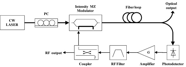
Figure 1 Basic structure of an optoelectronic oscillator based on a delay line (an optical fiber loop).
Fundamentally this oscillator is a delay line oscillator, and it is possible to use a very long delay line by way of an optical fiber loop, leading to very small losses even with a loop of some kilometers in length. Because of this long delay line, it is possible to obtain very low phase noise, which is the main property of interest of the OEO.
The oscillation frequency f0 depends on the global delay τ g , which is the sum of the electronic delay and the optical delay, τ g =τ e +τ op , and on an integer k, which is the mode number [1]. The global delay can be seen as that of an equivalent fiber loop length L, such as τ g =nL/c, where c is the velocity of the light in vacuum. According to the oscillation conditions, the oscillation frequency is given by ω 0k τ g =2kπ, and so

The spectrum is composed by closed spectral lines separated by the free spectral range of the oscillator, FSR
osc
; it can be deduced from (

The oscillator used in our experiment has been developed from the following elements. The laser is a multiple quantum well laser diode at 1535 nm (Fujitsu FLD5F6CX). The modulator is made of LiNbO 3 with an RF bandwidth at −3 dB of 12 GHz and optical insertion losses of 3.5 dB (Photline MX-LN-10); the optical attenuation is about 4 dB. The detector is a 15 GHz PIN receiver associated to a preamplifier (DA-LightCom DAL-15-OI). Three stages of amplifiers have been used: an ALC AWB2018-23–22 (23 dB gain and 18 GHz cutoff frequency), a Da-LightCom DAL-15-VAP (with a cutoff frequency of 15 GHz and a gain of 22 dB) and a DR-GA-10 also from Photline (15 GHz bandwidth and 26 dB gain). The filter has a center frequency of 8 GHz, a bandpass of 25 MHz and an insertion loss of 4 dB (BL Microwave BP8000-25/T-5TE01).
Measurements are performed with the E4446A spectrum analyzer from Agilent Technologies. The oscillation frequency is f0=8.004 GHz, as shown in figure 2. The power at the central frequency, approximately 3 dBm, is measured at the output of a 10 dB directional coupler (ref. C116-10/7–12.4 GHz from ATM). The RF output is in fact attenuated by 10 dB. The different modes are not completely filtered by the bandpass filter but one mode appears as predominant. The free spectral range FSR OSC is 201 kHz, with −34. dB suppression mode.
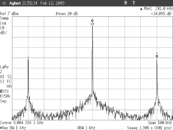
Figure 2 The oscillator spectrum of the OEO at a frequency of 8.004 GHz, in the case of a 1 km fiber loop.
From (
Thanks to our spectrum analyzer, it is possible to measure the phase noise of the OEO as shown in figure 3. In the case of 1 km optical fiber loop length, the measured value is -107.1 dBc Hz −1, which is a reasonable value.
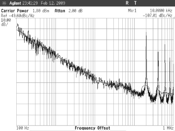
Figure 3 The phase noise of the OEO at a frequency 8.004 GHz, in the case of a 1 km fiber loop. The lines at 200 kHz, 400 kHz... from the carrier correspond to the other close modes attenuated by the filter.
2. Limitations of the OEO
2.1. Influence of the delay line, the optical fiber loop
There are some limitations on the performances of an OEO. First of all, because of the structure based on a delay line, there is a problem in the choice of the fiber loop length. A long fiber is necessary in order to have a very low phase noise, but the consequence is to decrease the FSR of the oscillator leading to very close spectral lines, which are difficult to eliminate with the RF filter. The solution to this tradeoff is to use a multiloop structure: a short fiber for avoiding the too close spectral lines and a long fiber leading to very low phase noise. In case of a double loop OEO, phase noise as low as -140 dBc Hz −1 at 10 kHz from the carrier has been reported [6]. Nevertheless, there is still a possibility of mode hopping.
The temperature changes have a great influence on the oscillation frequency. This phenomenon is easy to observe when the room temperature changes during the experiment. There are two possible reasons: the change in length of the fiber loop and the change in the refractive index. From (

For a single mode fiber, the typical values are ∂n/∂T≅ 1.2×10⁻⁵ °C −1, and so (1/n)/(∂n/∂T) ≅ 8.3×10⁻⁶ [7], and (1/L)/(∂L/∂T) ≅ 0.55×10⁻⁶ °C −1 (http://www.accuratus.com/fused.html). The most important effect is then the dependence on the change of the refractive index. The solution is obviously to control the temperature of the system (which is what we have done for the previously presented results) but, as the fiber loop can take a rather important volume, this control is not so easy to perform for a commercial apparatus. The idea is to replace the fiber loop with an optical resonator; nevertheless, it is important to keep in mind that for some applications the delay line structure with a fiber loop is necessary, for example in the case of refractive index measurement [2] or of tuning the oscillation frequency for radio over fiber applications [8].
2.2. Influence of the modulator
The highest frequency of the oscillator is mainly limited by the bandwidth of the modulator. Inorganic electro-optic modulators (such as lithium niobate LiNbO 3) are limited to approximately 100 GHz. That is the modulator we are using for our experimental study of the OEO. Even if this kind of modulator is rather stable, the optical bias point of the modulator depends on the one hand on the temperature change and on the other hand it changes because of the optical properties during the working operation and it is necessary to compensate this drift. It is possible to introduce two controls: one for the temperature and one for the compensation of the optical drift by determining its nonlinear behavior [9].
Because of their low dissipation factor, electro-optic polymer materials have very good microwave characteristics, and modulators operating up to the THz are considered as possible [10]. By using this kind of material, an OEO at 39 GHz was presented in 2002 with a phase noise of −70 to −80 dBc Hz −1 at 10 kHz from the carrier with an optical fiber length longer than 4 km [11]. The main drawback of the electrooptic material is maybe its rather low time stability [12, 13]. The material depends heavily on temperature and on the optical power injected into the component. Temperature control and compensation of the optical bias point compensation [9] are strictly required. At this time there is no real commercial product based on this material. Nevertheless, research is still going on into this kind of material, for example based on the classical DR1-PMMA [14]. Interesting results can be obtained in terms of half-wave voltage, for example, thanks to a push-pull structure, a Mach–Zehnder modulator has been realized with a 2.6 half-voltage with 2 cm long [14].
3. Microresonators for an OEO
Considering the drawbacks of the delay line, the fiber loop can be replaced by a microresonator. The materials can be polymer, silica or silicon on insulator. With such a solution, the size of the OEO is greatly reduced and it should be possible to implement better temperature control. Using a microresonator instead of the fiber loop can lead to other kinds of applications based on a change in its free spectral range. It must be sensitive to specific products for detecting chemical or biochemical matter. It is also important to remember that with a structure based on a microresonator instead of a delay line, there is no need for a RF filter: the microresonator acts as the filter by way of the FSR selecting the oscillation frequency. There is only one frequency and so no mode hopping.
In order to use a microresonator as a replacement for the fiber loop, the condition is that they have a similar quality factor. It is considered that the storage time in the resonator is equal to the propagation time in the fiber loop. At an oscillation frequency of 8 GHz, a fiber loop of 500 m length will be equivalent to a resonator with a quality factor of 2.5×10⁵,

3.1. Polymer materials
Polymer material can also be used for designing micro-resonators. It can be used for microcavities, such as a micro-disk or micro-stadium shape. For example [15], a value of Q=6000 has been obtained with a micro-stadium used for achieving a microlaser. Other shapes of polymer based microresonators are also studied, such as microrings. One of their application domains could be bio or chemical sensors, the contact with some specific liquids leading to a change in the FSR.
3.2. Fused silica microspheres used as resonators
These optical micro-cavities operate in whispering gallery mode. In a combined experimental and theoretical study, some values corresponding to microspheres made of BK7 have been published [16]. For example, with a diameter of 15 μm, at a wavelength of λ=1556.55 nm, an FSR of 17.380 ± 0.005 nm and a quality factor Q=4000 have been found; for a diameter of 100 μm and at λ=1553.99 nm, the FSR is 2.655 ± 0.003 nm and Q=2.3×10³. The effective index is approximately n eff ≈1.45.
The FSR can be expressed in the frequency domain by

Therefore, in the case of the 15 μm diameter microsphere, FSR osc =2.15×10¹² Hz, and for the 100 μm diameter microsphere, FSR osc =330 GHz. Clearly, this kind of microsphere is too small to obtain a usable FSR osc in an OEO working at 'low' frequency (from some GHz to some tens of GHz maximum). The maximum diameter already obtained for a microsphere is around 400 μm. The solution with a microsphere should be dedicated to a very high oscillation frequency OEO up to 100 GHz. In this case, there is a problem with the choice of the modulator, as mentioned before.
3.3. Resonators based on SOI material
The following microresonators are working as wave guides. They have been chosen here to realize a microresonator with silicon on insulator technology. In this way it should be possible to go toward integration of the different functions of the OEO on a single chip. The resonator has been designed according to the characteristics of the previously presented oscillator.
The complete structure of the resonator is shown in figure 4. The gap between the resonator itself and the input and output guides is 2.2 μm. There are two outputs: the 'through' at Port-1 and the 'drop' at Port-2. The total length of the resonator should be such that after one turn the optical wave is in phase with itself.

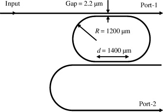
Figure 4 Resonator shape as a stadium: 'through' is obtained at Port 1 and 'drop' at Port 2.
Considering an effective index equal to 2.918, the final length should be L=12 851 μ m. From a simulation study performed at IEF, it has been found that a tradeoff between the global size and losses due to the radius of the guide leads to the choice d=1400 μ m and R=1600 μ m [17]. The waveguide size is given in figure 5. One must note the very small height of the guide: only 30 nm.
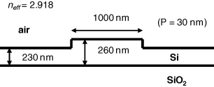
Figure 5 Design of the waveguide.
The first measurements have been conducted on this microresonator. The test at Port-1 has been conducted with variations of the wavelength from 1554 nm to 1555 nm, leading to the results presented in figure 6. A tunable laser Agilent 81940A has been used.
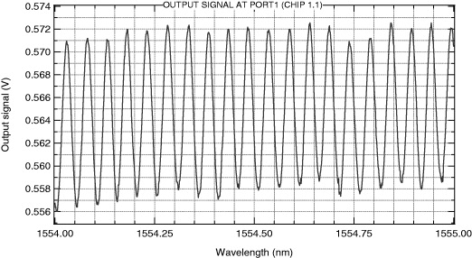
Figure 6 Transmission spectrum of the stadium resonator made on SOI at Port 1.
A zoom on the transmission spectrum figure is given in figure 7 for estimating the FSR, which is found to be equal to 50 pm and the FHWM to be 26 pm at the wavelength of 1554.40 nm. So the quality factor should be greater than 3.11×10⁴. This value seems to be under evaluated because some other measurements show a better contrast for the output signal, leading to a higher value of the quality factor. The finesse is in this case of only 1.92. The wavelength free spectral range of 50 pm corresponds by using (
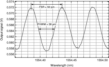
Figure 7 Zoom on the transmission spectrum for determining the FSR and quality factor.
4. Conclusion
The OEO could be a very promising system for applications in various domains, such as telecommunications or sensing systems. Thanks to the outputs with RF signals or optical signals, the oscillator is a perfect communication tool. An important improvement to the OEO in terms of spectral properties would be obtained by integrating the different elements; the choice of the appropriate substrate materials would then be fundamental. Different solutions with the same substrate for both the modulator and the resonator can be imagined, like using polymer material or silicon on insulator. Combining modulators and resonators in either polymer material or silicon material is possible. But silicon on insulator would allow the inclusion of a photodetector on the same chip. And in this case, why not also include the RF devices? Unfortunately, the integration with the polymer material will not be so complete. One of the drawbacks of polymer materials is the high dependence of their properties on the temperature. This is an obstacle for including them close to RF devices and thus achieving perfect integration. Otherwise, there are no photodetectors based on polymer material. Microspheres made of fused silica are, of course, usable for very high frequency OEO but for an integrated system there is a need for special packaging for placing the sphere between the modulator and the detector. Finally, a very promising material seems to be the silicon on insulator for the best integration possibilities. Silicon photonics is still promising!
Acknowledgments
The authors would firstly like to thank the EADS foundation for supporting their research activities in the field of 'Photonic devices based on electro-optic polymer materials' and the corresponding applications, and secondly the PRES UniverSud for its support for the study of microresonators.