
Abstract
Applications of ion beam techniques (IBA and IBMM) on nanoscaled thin films of selected materials (e.g. magnetite Fe3O4, uranium nitride UN) are presented. 1 MeV Ar+ and Kr+ ion beam with different ion fluences in the range of 1015–1017 ions cm−2 have been used to modify the film interfaces. Selected heterostructure interfaces were treated by subsequent thermal annealing. By analyzing the results obtained for the films in three different states (as-deposition, after annealing and after ion irradiation), the effects of ion beam mixing and interdiffusion were determined.
Export citation and abstract BibTeX RIS

Content from this work may be used under the terms of the Creative Commons Attribution-NonCommercial-ShareAlike 3.0 licence. Any further distribution of this work must maintain attribution to the author(s) and the title of the work, journal citation and DOI.
1. Introduction
One of the themes of the Seventh Framework Programme (FP7) for research and technological development in Europe concerns 'Nanosciences, Nanotechnologies, Materials and new Production Technologies' (FP7-NMP). One of the FP7-NMP topics, 'Modeling of multilayer interfaces for high performance materials design', focuses on enhancing the knowledge of phenomena and physical properties in nanoscaled heterostructures of technologically important materials which meet future applications and developments of nanoscience and nanotechnology, such as spintronic devices/sensors, magnetic sensors and switches, magnetic random-access memories (MRAM), magnetic tunnel junctions (MTJs) and model materials used in corrosion and catalysis.
We are interested in controlling and modeling interfaces of thin film systems with optimal structures, proper morphology and desired properties. Ion beam analysis (IBA) techniques are employed to investigate the nanoscaled heterostructure thin films in the as-grown state and after modification by ion beams (Ion Beam Modification of Materials (IBMM)) and/or thermal annealing. IBA and IBMM have been widely used in materials science, such as studies and improvement of materials properties, like adhesion, hardness, interface engineering and fabrication of semiconductor devices by implantation. In our study, several materials with a strong potential for applications have been selected, such as magnetite Fe 3 O 4 (spintronic devices/sensors at room temperature) [1–4], titanium oxynitrides TiN x O y (photocatalysis) [5], uranium nitride UN (nuclear fuels) [6], uranium-iron UFe x (interesting combined 5f–3 d magnetism) [7], highly-ordered Pd–Fe alloy multilayers (high-density recording materials) [8], and hydrides of the Ti–TiO 2–Ti system (hydrogen storage materials) [9]. In this limited-length paper, we concentrate on a detailed analysis of the ion beam mixing effect and interdiffusion obtained for Fe 3 O 4 films. Some results recently obtained for UN systems will be also presented.
2. Experimental
Rutherford backscattering (RBS) experiments (2 MeV He + ions, scattering angle of 171°) and RBS channeling (RBS-C) experiments (1.5 MeV He + ions, scattering angle of 160°) were performed at the Institute of Nuclear Physics of the Johann von Goethe University in Frankfurt/Main (IKF-Frankfurt). For data evaluation, the computer code SIMNRA [10] was used, taking into account the electronic stopping power data by Ziegler and Biersack, Chu Yang's theory for electronic energy-loss straggling and Andersen's screening function to Rutherford cross-section. The contribution from double and/or multiple scattering into the RBS spectra was taken into account using the calculating facilities of SIMNRA.
RBS film thickness is determined from the energy loss of the projectile He + ions and/or from the total number of counts of the signal (peak-area). The film thickness t is related to the energy difference ΔE (i.e. the energy width of the RBS signal) between ions scattered from the front surface (KE0, where E0 is the primary energy and K is the kinetic factor) and those from the rear surface (E1, t ) of the film (i.e. from the film surface and those from the film-substrate or film-film interface) by the formula [11]

where N is the film density and is the stopping cross-section (ε-factor). The relation between the film thickness t and the total number of counts of the signal A0 is [11]

where σ(E0) is the Rutherford cross-section, Ω is the detector solid angle, Q is the total numbers of incident particles hitting the target (charge) and θ is the scattering angle. The RBS fit is simulated for the (Nt) product—the areal density (the number of target atoms per unit area, in [1015 atoms cm −2]) which can be converted into the layer thickness in [nm] by using the mass density value of the bulk and/or the layer density value determined from x-ray reflectometry (XRR) measurements.
Irradiation experiments were carried out at the 2 MV Van de Graaf accelerator of the IKF-Frankfurt. Ar + and Kr + ions with energy of 1 MeV were used. The ion fluences were in the range of 1015–1017 ions cm −2. The irradiation parameters for e.g. magnetite thin films are summarized in table 1. The sample temperature was held constant at either −50 °C or +5 °C during irradiation. For studying the interdiffusion process, selected heterostructure interfaces were treated by subsequent thermal annealing under partial pressure of Ar gas at different temperatures and at for different annealing times.
Table 1. The irradiation parameters. The ion ranges, S e and S n are calculated for the Fe 3 O 4/MgO and Fe/MgO system (the values marked in bold and italics, respectively).
| Ion energy (MeV) | 1 | 1 |
| Beam spot size (mm) | 8 | 8 |
| Current density (nA cm −2) | 700–1300 | 800–1000 |
| Ion dose (1016 ions cm −2) | 0.4–30.0 | 0.15–4.0 |
| Temperature (°C) | −50, +5 | −50, +5 |
| Ion range (nm) in Fe3 O4 /iron | 577/418 | 334/241 |
| S e (eV Å−1) in Fe3 O4 /iron | 151/199 | 101/137 |
| S n (eV Å−1) in Fe3 O4 /iron | 30/41 | 147/199 |
3. Fe 3 O 4/MgO(001) and Fe 3 O 4/Fe/MgO(001) films
Magnetite (Fe 3 O 4) has attracted much attention due to its interesting electronic and magnetic properties and its wide use in technology, such as in magnetic recording media, corrosion and catalysis. This material is referred to as one of the semi-metallic materials having a full spin polarization at the Fermi level. It has a high critical temperature (the Néel temperature is 858 K) and thus it has recently been viewed as a promising material for spintronic applications at room temperature. For reviews of the structure and electromagnetic properties of Fe 3 O 4, see e.g. [12], [13, 14] and references therein. The growth of magnetite thin films with excellent crystalline quality (crystalinity) is especially important, since most spintronic devices are based on thin film technology. For reviews of film-growth, characterization and investigation of the thermodynamic properties of magnetite thin films, see e.g. [15] and references therein. For molecular beam epitaxial (MBE) growth of magnetite films, the MgO(001) substrate has frequently been used due to the fact that the lattice mismatch is very small (0.31%). The traditional method is to deposit a magnetite layer directly on a MgO(001) substrate (denoted in this work as a single-layer magnetite film or Fe 3 O 4/MgO(001) film). Another possibility is to deposit a magnetite layer on an epitaxial Fe(001) buffer layer grown epitaxially on the MgO substrate [15] (i.e. the bi-layer magnetite film or the magnetite-on-Fe-film or Fe 3 O 4/Fe/MgO(001) film). The measurements by e.g. using conversion electron Mössbauer spectroscopy (CEMS) have revealed a surface oxidation and Mg out-diffusion from MgO substrate into the film for single-layer films, whereas no Mg diffusion and Mg segregation to the surface was observed for bi-layer films, since it could be prevented by the Fe layer [15]. Therefore bi-layer magnetite film is considered a solution to obtain a stoichiometric Fe 3 O 4 layer on the film-surface. However, the extra Fe layer would introduce a large lattice mismatch (4%) at both Fe 3 O 4/Fe and Fe/MgO interfaces, which can degrade the crystallinity of the film [3]. It would be meaningful to use an ultra-thin Fe layer, since it can be strained to MgO substrate and would follow the lattice template of MgO substrate, and the strained Fe layer would allow Fe 3 O 4 epitaxy on it and thus the crystal quality of Fe 3 O 4 layer would be improved. However, if the films are thin, it is impossible to separate the Fe signal of the Fe 3 O 4 film from that of the Fe layer in the RBS spectra.
In our study, we used both single- and bi-layer magnetite films with the thickness of each layer ranging from 10 nm (i.e. the thin films; sample T1 and T2 listed in table 2) to 25–100 nm (the thick films; sample S1–S8). The layer thickness of thicker films in fact has been pre-estimated using SRIM code [16] to maximize the mixing effect at the two interfaces separately by using 1 MeV Ar + and Kr + ion beams. Six samples underwent a post-annealing treatment (ann.): the single-layer films (S1, S2, S3) and the bi-layer films (S4, S6, S7) were annealed for 30 min, respectively, at 520 and 800 K. For underlying the annealing effect, we studied two bi-layer films with similar thickness, one under post-annealing (S6) and another (S9) without annealing (non-ann.). In order to get clear features of the Fe layer beneath the Fe 3 O 4 layer, we also investigated a bi-layer film with a thin Fe 3 O 4 layer (∼8 nm) deposited on a thick Fe buffer (sample S8).
Table 2. RBS and XRR analysis of single- and bi-layer magnetite films grown epitaxially on MgO substrates. The values given in brackets are the layer-thickness values for the stoichiometric Fe 3 O 4 and Fe layer determined by RBS analysis. d is the layer-thickness and r is the roughness determined by XRR analysis.
| T1 | (9.5 nm) (Fe 0.93 Mg 0.07)3 O 4/MgO | 10.90 | 0.90 | 0 | 0 | |
| T2 | (12 nm) Fe 3 O 4/(6 nm) Fe/MgO | 13.90 | 0.75 | 6.00 | 0.40 | |
| S1 | (105.5 nm) Fe 3 O 4/MgO | |||||
| S2 | (21.9 nm) Fe 3 O 4/MgO | 19.79 | 1.10 | 0 | 0 | |
| S3 | (52.7 nm) Fe 3 O 4/MgO | 49.98 | 0.55 | 0 | 0 | |
| S4 | (29.5 nm) Fe 3 O 4/(24.2 nm) Fe/MgO | 29.00 | 1.00 | 28.10 | 1.00 | |
| S6 | (59.6 nm) Fe 3 O 4/(29.0 nm) Fe/MgO | 54.7 | 0.90 | 28.24 | 0.90 | |
| S7 | (105.4 nm) Fe 3 O 4/(28.5 nm) Fe/MgO | |||||
| S9 | (58.5 nm) Fe 3 O 4/(29.1 nm) Fe/MgO | |||||
| S8 | (8.4 nm) Fe 3 O 4/(41.3 nm) Fe/MgO | 8.1 | 0.65 | 40.92 | 0.27 |
3.1. The composition and crystallinity of as-grown magnetite films
In figure 1, the random RBS spectra (at a tilted angle φ=40°) of different films revealing different features are shown: (i) the spectrum with only a single Fe peak and no (separated) O signal for a single Fe 3 O 4 layer, (ii) the spectrum with an overlapped Fe signal from Fe in the Fe buffer and Fe 3 O 4 layer and a distinguished O-peak from the Fe 3 O 4 film and (iii) the spectrum with well-separated Fe and O peaks from the two layers. The simulated spectra by SIMNRA are shown as solid lines in the same figure. The estimated layer thickness by SIMNRA is given in table 2. The RBS spectra of single-layer magnetite films (sample T1 and S1–S3) are characterized by a sharp Fe peak (around the energy of 1.5 MeV), a steep Mg edge and an O edge from the MgO substrate (around 0.95 MeV and 0.70 MeV, respectively).
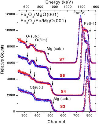
Figure 1 Random RBS spectra (at tilted angle φ=40°) for selected Fe 3 O 4/MgO(001) film (sample S3) and Fe 3 O 4/Fe/MgO(001) films (S4, S6, S7) with different layer-thicknesses (see table 2). The simulated RBS spectra are shown by solid lines.
Increasing the film thickness (e.g. from ∼10 nm (sample T1) to 22 nm (S2), 53 nm (S3) or 105 nm (S1)) leads to an increase in the width and intensity of the Fe peak and a shift to a lower energy of both the Mg- and O-edge, but the oxygen signal from the Fe 3 O 4 film and MgO substrate always overlaps and thus no separated O-peak can be observed for the single-layer films. For the bi-layer films, the presence of the Fe buffer between the Fe 3 O 4 film and the MgO substrate implies an appearance of a distinguishable O-peak (sample T2 or S4). Thus the oxygen signal of the Fe 3 O 4 film becomes more pronounced with increasing layer-thickness of either Fe film or Fe 3 O 4 film. A much higher Fe-peak was observed for the bi-layer films since it was a combined Fe signal coming from both the Fe 3 O 4 and the Fe layer. With increasing thickness of both layers, a large Fe peak with a double feature related to the backscattered signal from the Fe atoms in the Fe buffer layer (the maximum) and in the Fe 3 O 4 layer (the shoulder on the right-hand side of the maximum) was observed (sample S6). The shoulder feature became more pronounced further increase in the thickness of the Fe 3 O 4 layer (sample S7).
The RBS experiments were often performed about one week after that the samples were exposed to air. For the thin single-layer film (d=10 nm, sample T1), the film composition was found to be Fe 3−x Mg x O 4 (x=0.21; i.e. the spinel layer) as a consequence of Mg diffusion (3%) into the Fe 3 O 4 film [1]. For the thicker films (S1–S3), no magnesium was found in the topmost surface layer, indicating that there is no segregation of Mg atoms to the surface. However, at the film interface exists a spinel layer due to the Mg out-diffusion from the substrate (with a thickness d<5 nm and the x-content is x=5–10%). For the bi-layer films, as expected, the surface layer is a stoichiometric Fe 3 O 4 layer. However, for the samples under post-annealing (T2, S4, S6, S7), the RBS analysis indicated a thicker Fe 3 O 4 layer and a much thinner Fe layer (in comparison with the nominal thickness). In addition, a wustite layer was found to be located between the Fe layer and MgO substrate (d<5 nm). Even for the sample S9 without post-annealing, the thickness of the Fe buffer layer is only 29 nm, much smaller than the nominal thickness of 50 nm. For the sample S8 without post-annealing and with a very short time deposition of the Fe 3 O 4 layer, the thickness of the Fe buffer layer is 41.3 nm, which is quite close to the nominal one (50 nm).
Moreover, no wustite layer was detected in this case. Thus the larger thickness value of the Fe 3 O 4 layer and the existence of the wustite layer in samples T2 and S4–S9 suggested that the top and bottom part of the Fe layer was oxidized, which occurred during the growth of the Fe 3 O 4 film rather than during post-annealing.
The RBS-C experiments were performed on several films to check the film crystallinity. The normalized angular yield curves (with respect to the maximal backscattered yield of the random spectra) for Fe in the film for selected magnetite films are shown in figure 2. For all of hose films, the minimum yield for Mg was determined to be χ min (Mg)=2–5%, indicating a perfect crystal quality of the MgO substrate.

Figure 2 The channeling curves of Fe with respect to the [001] direction showing (a) only a single minimum for sample S2 (21.9 nm Fe 3 O 4/MgO(001) and S4 (29.5 nm Fe 3 O 4/24.2 nm Fe/MgO(001)) and (b) a double minimum for sample S6 (59.6 nm Fe 3 O 4/29.0 nm Fe/MgO) and S8 (8.4 nm Fe 3 O 4/41.3 nm Fe/MgO(001)). The channeling curve for Mg in the substrate (Mg(sub.)) was shown in (a).
For the single-layer magnetite films, the full-width at half-maximum (FWHM) for Fe in the film (χ min (Fe)) was always below 20%. For instance, for sample S2 (21.9 nm Fe 3 O 4/MgO film) χ min (Fe)=18%, ψ1/2(Fe)=1.86°. For the bi-layer film S4, the angular yield curve revealed only one minimum (figure 2(a)) with a larger χ min (Fe) value and a lower ψ1/2(Fe) value (χ min (Fe)=60%, ψ1/2(Fe)=1.52°), indicating that the crystal quality is lower. For sample S6 (e.g. samples with a separation of the Fe signals and a visible O-peak in the RBS spectra), a double minimum was revealed in the channeling curve (figure 2(b)). The deep minimum (χ min (Fe)=31%, ψ1/2(Fe)=1.40°) at a normalized tilted angle φ=0° was considered to be as a channeling result through the surface Fe 3 O 4 layer, while the minimum-shoulder feature located at the right hand side (χ min (Fe)=75%) was attributed to the channeling effect of the Fe film. The angle-difference between the two minima was 2 degrees. For sample S8, two deep minima were clearly revealed in the channeling yield curve (figure 2(b)). The wider minimum (χ min (Fe)=60%, ψ1/2(Fe)=1.11°) and the narrow minimum (χ min (Fe)=55%, ψ1/2(Fe)=0.64°) were attributed to the channeling respectively of the Fe 3 O 4 and the Fe layer. In this case, the angle-difference between the two minima was equal to 2 degrees. In brief, the RBS-C results confirm that (i) the single-layer magnetite films always possess good crystallinity, (ii) for the bi-layer films, the lattice mismatch at both interfaces largely influences the channeling (implying a much higher value of χ min (Fe) and a lower value of ψ1/2(Fe)), (iii) the well-separated two minima in the channeling curves for the bi-layer films reveal the channeling effect in each layer indicating that each layer possesses good atomic arrangements, (iv) the post annealing does not influence the channeling, since there is no visible difference in the channeling between annealed and non-annealed samples (sample S6 and S9), (v) the minimum yield value for the bi-layer films is χ min (Fe)>50%, mainly due to the lattice mismatch at the Fe/MgO interface and (vi) the lattice mismatch at the Fe 3 O 4/Fe interface seems to not imply a chaotic atomic disorder but rather to make a change in the orientation (of 2 degrees) between the Fe atomic rows in the Fe layer and the Fe 3 O 4 layer.
XRR measurements have been performed on selected single- and bi-layer magnetite films to determine the absolute values of the film-thickness and film-density independently from the RBS measurements. The XRR parameters are given in table 2. In all cases, the film densities of the magnetite layers and Fe layers are found to be, respectively, ρ(F 3 O 4)=5.2–5.4 g cm −3, ρ(Fe)=7.8–7.9 g cm −3, very similar to the bulk density of magnetite (5.21 g cm −3) and iron (7.87 g cm −3), confirming the good stoichiometry of the films. The XRR results confirmed the presence of only one single layer on the MgO substrate for the directly deposited Fe 3 O 4/MgO films and of two-layers for the bi-layer magnetite films. The wustite layers would not be revealed from the XRR measurements, since the density of such layers is very close to that of the MgO substrate. In general, a good agreement for the layer thickness was obtained between the RBS and XRR results.
3.2. Interdiffusion and ion beam mixing effect in thin magnetite films
The experimental results and analysis of the interdiffusion effect (under thermal annealing in a partial Ar gas atmosphere) and ion beam mixing effect (under 1 MeV Ar + ion irradiation) for the thin single- and bi-layer magnetite films (sample T1 and T2 in table 2) have recently been published [2, 3]. This is illustrated in figure 3. For the single magnetite film, annealing largely promoted the Mg out-diffusion from the MgO substrate into the film, leading to an increase in the x-value of the spinel layer ((Fe x Mg 1−x )3 O 4) and formation of a Mg-mixed wustite layer (Fe y Mg 1−y O) in the interface. The enhanced Mg diffusion largely destroyed the film crystallinity indicated by a large increase of the minimum yield of Fe (χ min (Fe) > 62%) [2]. Although the enhancement of the Mg diffusion into the film implies a change in the film density, the difference in the layer-density of the two layers (i.e. the spinel and wustite layers) was large enough and thus they were still distinguishable from the XRR measurements. For the magnetite-on-Fe film (the bilayer film), upon annealing, the Fe layer was oxidized completely, but the pure Fe 3 O 4 layer on the surface was preserved. The enhanced Mg and Fe diffusion led to the formation of a spinel layer beneath the (surface) Fe 3 O 4 layer and Mg-mixed wustite layers at the interface. Thus the pure-Fe 3 O 4-spinel-wustite geometry is preserved upon further annealing, despite the fact that increasing temperature and annealing time leads to an increase in the Mg and Fe content of both spinel and wustite layers, as well as of the thickness of the interface zones. Ion irradiation of the single-layer film (1 MeV Ar + ion, φ=1015–1016 ions cm −2) induced a strong Fe mixing in the MgO substrate revealed by a visible lowering and broadening of the Fe peak in the RBS spectrum. The thickness of the spinel phase was only 4.5 nm, while the thickness of the wustite phase increased up to 23 nm. The Fe content decreases largely, from 35% in the first wustite layer to 5% in the deeper layers. For the bi-layer film, the pure Fe 3 O 4-on-pure-Fe-layer geometry of the film is well preserved under ion irradiation (with a similar ion fluence) despite the fact that the layer thickness was changed. The strong Fe mixing created a large interface zone (23 nm) having a wustite-type phase. However, only a small change in the Fe peak was observed in the RBS spectra due to the fact that the dominant contribution to the Fe peak came from both the magnetite and pure ion layer (which was well preserved under ion irradiation). It is crucial that our investigations show that the stochiometric Fe 3 O 4 layer of the magnetite-on-Fe film is well preserved upon annealing and/or ion irradiation.
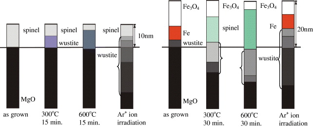
Figure 3 Illustration of the annealing and ion mixing effect for the thin magnetite films: (a) the Fe 3 O 4/MgO(001) film-sample T1 and (b) the Fe 3 O 4/Fe/MgO(001) film-sample T2. The layer thicknesses are drawn proportionally with respect to the values estimated from the RBS and XRR measurements. The solid line indicates the original separation between the film and the MgO substrate. Different colours indicate different Mg and Fe composition in the spinel (Fe 3−x Mg x O 4) and wustite (Fe y Mg 1−y O) layers.
3.3. Ion beam mixing effect in thick magnetite films
Samples S1, S2, S6 and S8 were subjected to ion irradiation by 1 MeV Ar + ions beam, while samples S3, S4, S7 and S9 were irradiated by 1 MeV Kr + ions with different ion fluences. As an example, the RBS spectra of irradiated Fe 3 O 4/Fe/MgO(001) film-sample S6 by 1 MeV Ar + ions are shown in figure 4(a). All spectra were collected at the titled angle of 10°. The values of ion fluences are given in the figure. Mixing-like effects between the (metallic) Fe layer and the (oxide) MgO substrates can be seen clearly at the back edge of the Fe signal and the front edge of the Mg signal. The mixing effect at the Fe-Fe 3 O 4 interface was revealed only by a change in the relative intensity of the Fe peak and the shoulder-like feature, since it corresponded to only a change in the Fe and O component within the layers. Upon irradiation with a small ion fluence (ϕ<5.0×10¹⁶ ions cm −2), the interdiffusion led to a change in the slope of the Fe peak. It is rather a small but quite a significant effect characteristic of metal/oxide systems. Upon exposing the sample to an Ar + ion beam longer than t>2 h (e.g. at a higher ion fluence ϕ>12.0×10¹⁶ ions cm −2), the signal from carbon became visible in the RBS spectra resulting from a thin carbon layer on the sample surface due to contamination. With increasing ion fluence, for ϕ>15.0×10¹⁶ ions cm −2, a very strong Mg out-diffusion and a large mixing effect were revealed: a large change is observed in the slope of the Mg-edge and bump-like features appear at the energies below the Mg edge and the oxygen peak. Those features become very pronounced upon irradiation with a larger fluence ϕ=26.0×10¹⁶ ions cm −2. A comparison of the Fe peak before and after Ar ion irradiations is shown in figure 4(b). The mixing is shown by a relative change in the peak intensity and peak width, as well as an appearance of the non-zero background at the left hand side of the peak. Our primary analysis indicated that the pure Fe 3 O 4 layer on the surface was still well preserved under irradiation with ϕ<10×1016 ions cm −2 although the layer thickness decreased (d<10 nm).
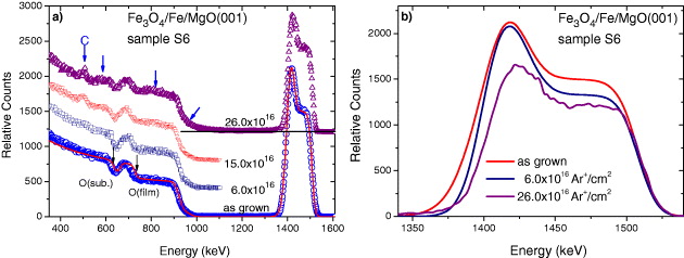
Figure 4 (a) RBS spectra of the thick Fe 3 O 4/Fe/MgO(001) film-sample S6 irradiated with a 1 MeV Ar + ion beam with different ion fluences. The strong mixing effect was indicated by e.g. the bump-like features marked by additional arrows and a big change in the intensity and width of the FE peak. (b) A comparison of the Fe-peak in the as-grown state with those after Ar + ion irradiation. The random RBS spectra were taken at the titled angle of 10°.
The RBS spectra of irradiated Fe 3 O 4/Fe/MgO(001) film-sample S9 by 1 MeV Kr + ions collected at the titled angle of 10° are shown in figure 5(a). In all cases, no carbon contamination was observed since the total irradiated time was much shorter (<1 h). Unlike the case with Ar + ion irradiation, the Kr + ion irradiation even if with a small fluence (ϕ=0.6×10¹⁶ ions cm −2) already created such a strong Fe-Mg mixing revealed by a non-zero background between the Fe peak and Mg edge (see the insert figure 5(a)) as well as the large change in the slope of the Mg-edge. A much larger change was also observed for the Fe peak shown in figure 5(b). Our primary analysis indicated that the pure Fe 3 O 4 layer on the surface could still be preserved only under the Kr + irradiation with ϕ< 0.6×10¹⁶ ions cm −2. The detailed analysis of the ion beam mixing effects (extracting the concentration profile of the layer component from the RBS data, estimating the mixing rate and diffusion rate . . .) in thick magnetite films are in progress.
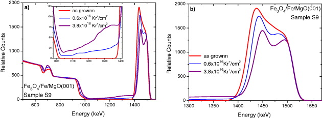
Figure 5 (a) RBS spectra of the thick Fe 3 O 4/Fe/MgO(001) film-sample S9 irradiated with a 1 MeV Kr + ion beam with different ion fluences. Inset: enlargement of the feature at the left hand side of the Fe peak reveals an enormous mixing effect. (b) A comparison of the Fe-peak in the as-grown state with those after Kr + ion irradiations. The random RBS spectra were taken at the titled angle of 10°. To guide the eyes, the data are shown by lines.
4. Uranium nitride films
Uranium mononitride (UN), having a high melting point (∼2850 °C), high density (14.32 g cm −3) and high thermal conductivity (13 W mK −1), is considered as one of the advanced nuclear fuels for fast reactors [17], and thus increasing attention has recently been paid to this material. Moreover, studies of uranium nitride are largely motivated by fundamental research issues, since only a small ordered moment of 0.75 μ B U −1 was found in the antiferromagnetic state below T N =53 K in this compound indicating the itinerancy of 5f electrons. The dynamical properties of nanoscaled UN thin films are found to be significantly different from those of the corresponding bulk materials. A large influence of the microstructure on the formation of magnetic moments and magnetic ordering was revealed in UN thin films prepared by reactive sputter deposition, although the stoichiometric UN phase (with a cubic-faced-centered structure (space group Fm m) and a lattice parameter a=4.8897 Å) was dominant in the films [18, 19]. An increased disorder with decreasing deposition temperature (T s ) leads to the suppression of the long-range antiferromagnetism: a glassy magnetic behaviour was observed in the UN film deposited at high temperatures (up to T s =350 °C), while the Pauli paramagnetic behaviour was found in the film deposited at the lowest temperatures (T s =−200 °C). We have determined the concentration depth profiles and the interdiffusion of the UN films in the as-grown state and after irradiation by a 1 MeV Ar + ion beam with different ion fluences in the range of 1016 ions cm −2 [6]. The most interesting results of ion beam mixing were obtained for the film deposited at room temperature denoted as UN/SiO 2 (+25 °C) film, as shown in figure 6. In the as-deposited state, a very broad signal in the energy range from 1150 to 1870 keV as a result of a uranium signal from the film, a small up-turn around 750 keV indicated the backscattered signal from nitrogen atoms located on the front-surface of the film, a visible rising-edge around 580 keV related to the Si signal from the substrate and a non-zero background between the Si-edge and the U-peak as a consequence of uranium diffusion into the SiO 2 substrate (figure 6(a)). The nitrogen signal in the entire film induced only an additional increase of the background below 750 keV and no clear backscattered signal from the nitrogen atoms from the rear-surface of the film was shown. No distinguished feature related to the oxygen signal from the substrate was observed, since it was mixed with that from nitrogen in the film and thus 'hidden' in the rising-edge below 530 keV. A very small peak was observed for which the energy position was well fitted to the helium–oxygen binary collision contributed to the oxygen signal from the surface layers. The linearly-increased plateau in the energy range of 1300–1500 keV revealed the RBS signal coming from the good stoichiometric UN layer in the film (i.e. the U-content and N-content both equal to 50%). A strong decrease in the peak-intensity observed in the energy range of 1600–1900 keV indicated the existence of layers with lower uranium content (or in other words the nitrogen-excess layers) as a consequence of a short circuit of the U-target at the end of the film deposition. For this film, a distinguished additional peak-like feature was observed at an energy of 1200–1300 keV related to a U-excess layer (i.e. the U-content is higher than 50%) located between the stoichiometric UN layer and the SiO 2 substrate.
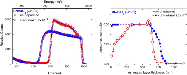
Figure 6 Comparison of the random RBS (markers) and SIMNRA simulated (lines) spectra (a) and of the U-concentration depth profile (b) for UN/SiO 2 (+25 o C) film in the as-deposited state and after irradiations by 1 MeV Ar + ion beam. The ion fluence (1016 ions cm −2) is given in the figure.
A large increase in the film thickness induced by ion irradiation was observed. The surprising fact in this case was an enlargement of the linearly increased plateau, indicating that ion irradiation leads to an establishment of the uranium content of 50% up to the topmost surface layer, i.e. the thickness of the stoichiometric UN layer increased significantly upon ion irradiation. Moreover, ion irradiation induced a large change in the layer-composition and enhanced diffusion in the interface zone, implying the disappearance of the U-excess layer. The change in composition and thickness of the individual layer of the target can be seen clearly by a transformation of the RBS spectra to the depth profile of the elements (figure 6(b)). The concentration profile consists of a few different zones with distinguished different compositions: the surface zone with mixed UN y -UO x layers, the UN y layer and the UN y –SiO 2 interface zone. For the as deposited UN/SiO 2 (+25 °C) film, the main layer consists of a 162 nm-thick N-excess layer (y>1) and a 240 nm thick stoichiometric UN layer. Ar + ion irradiation leads to the formation of a very thick layer with the exact value of 50% for U-content, as a consequence of atomic rearrangements in both the surface region and the interface, and thus the thickness of the stoichiometric UN layer increases and reaches 500 nm. Moreover, upon irradiation, the U-excess layer has disappeared and the spread of uranium atoms implies that the mixed UN y –SiO 2 layer is enlarged.
5. Conclusion
We have studied the surface and interface properties of selected nanoscale heterostructured thin films by ion beam techniques. The IBA performed on single- and bi-layer magnetite films (Fe 3 O 4/MgO(001) and Fe 3 O 4/Fe/MgO(001) films) with a layer thickness in the range of 10–100 nm confirmed that one could always obtain the stoichiometric Fe 3 O 4 surface layer for the magnetite-on-Fe films prepared by the MBE technique, i.e. by deposition of the Fe 3 O 4 layer on a Fe buffer layer deposited epitaxially on a MgO substrate. The channeling experiment indicated a good crystallinity of the single-layer magnetite films. A larger value of the minimum yield of Fe (>50%) for the bi-layer films indicated a large influence of the lattice mismatch at the Fe/MgO interface on the channeling. The lattice mismatch at the Fe 3 O 4/Fe interface rather implies a change in the atomic orientation of 2° between the Fe atomic rows in the Fe layer and in the Fe 3 O 4 layer.
The IBMM experiments revealed that this stoichiometric Fe 3 O 4 layer of the bi-layer magnetite films could be well preserved upon thermal annealing as well as upon irradiation by 1 MeV Ar + ion irradiation with an ion fluence of ϕ=1016 Ar + ions cm −2. This stoichiometric Fe 3 O 4 layer on the surface can survive even if under 1 MeV Kr + ion irradiation with a small ion fluence ϕ=5×10¹⁵ Kr + ions cm −2.
The results obtained for uranium nitride UN thin films indicate that, by ion irradiation, it is possible to modify the element content in this thin film system to establish the required uranium content of 50% in the film, i.e. establish the uranium mononitride layer (the stoichiometric UN). Our investigations have shown that IBMM opens up the possibility of modification and/or tailoring of the as-deposited films in order to obtain films with the required properties and/or required thickness.
Recently, systematic investigations of an ion mixing effect by using a 1 MeV Ar + and Kr + ion beam with an ion fluence in the range ϕ=1015–1017 ions cm −2 have been performed on a series of single- and multiple-layer thin films of (Pd, Fe) alloys prepared by the sputtering technique. The data analysis is in progress.
Acknowledgments
This work was financed by the German Federal Ministry of Education and Research (BMBF project MOE 07/R61) and by the German Academic Exchange Service (DAAD project D/08/07729) between UP Kraków and TU Darmstadt (Dr A G Balogh), and by the Polish Ministry of Science and Higher Education (MNiSW project Nr 651/N-DAAD/2010/0). The magnetite thin films were prepared within the scope of cooperation with Professor J Korecki (AGH Kraków). The UN films were prepared by Professor L Havela (Charles University, Prague) and Dr T Gouder (ITU, Karlsruhe).