

Abstract
With the consumption of energy throughout the world that is continually increasing and with continuous decreasing of the main sources of world's energy, such as fossil fuels, using green and renewable energies such as wind and sun seems necessary. Solar cells are the main devices to convert the solar energy into electricity. Among different types of solar cells, dye sensitized solar cells (DSSCs) that are types of nanostructured solar cells have been the subject of a lot of ongoing investigations due to low construction costs and other benefits. In this study, the role that Au metal nanoparticles (NPs) play in improving the efficiency of DSSCs is studied. DSSCs were fabricated by using red tea as a natural dye sensitizer. The Au NPs were synthesized and functionalized with carboxyl group and then were used in the photoanode of the fabricated DSSCs. Operation of this cells in the presence of the NPs and the role of the ligand in protecting NPs and DSSC efficiency was studied. Results show that by reducing resistance of charge transfer in the photoanode of the cell and increasing the absorption through local surface plasmon resonance effect the NPs can increase cell efficiency.
Export citation and abstract BibTeX RIS

Original content from this work may be used under the terms of the Creative Commons Attribution 3.0 licence. Any further distribution of this work must maintain attribution to the author(s) and the title of the work, journal citation and DOI.
1. Introduction
In recent centuries, humans have employed fossil fuels as the primary energy source, and now we are facing serious energy supply problems [1]. Renewable energy such as sun and wind and nuclear power are the energy sources in the world that grow fastest, every one increasing by 2.5 percent per year. However, fossil fuels continue to supply almost 80 percent of world energy use through 2040. Natural gas is the fastest-growing fossil fuel in the outlook. Natural gas use throughout the world increases by 1.7 percent per year. The industrial department continues to account for the biggest share of delivered energy use; the world industrial department consumes over half of energy provided in the world in 2040. Regarding to the present policies and rules that limit the use of fossil fuel, worldwide energy-related carbon dioxide emissions arise from about 31 billion metric tons in 2010 to 36 billion metric tons in 2020 and then to 45 billion metric tons in 2040, this indicates 46-percent increase [2]. The type of energy source used to generate electricity is the main factor influencing emissions. Greenhouse gases absorb infrared radiation, thereby trapping heat and result in the warmer planet. Therefore, emissions greenhouse gas from developed countries must be strongly decreased, while newly industrialized countries must limit increases in  emissions. Thus, energy sources alternative to coal, oil and gas must be provided. For example, some electricity is generated through non-fossil fuel options such as nuclear, hydroelectric, or geothermal energy. The use of renewable energies, such as solar energy, can be a source of encouragement for the replacement of fossil fuels [3, 4]. In a lot of area of the world, concerns about security of energy supplies and the environmental results of emissions from greenhouse gas have spurred government policies that cover a planned increase in renewable energy sources [5]. But the outlook for coal could be changed substantially by any future national strategy or international agreements that their goal is to decrease or limit the growth of greenhouse gas emissions. Therefore, the requirement will be more important for energy alternative sources. A good procedure for producing energy using the natural resources is converting incident light of the sun to electricity via photovoltaic proceedings by solar cells. Such sustainable energy, which can be provided by sun, can be assumed as the cleanest one and renewable energy, which can provide the world's need for electrical energy by converting the sun's energy into electricity. Despite the lack of knowledge and unavailable suitable technology to demonstrate the project, photovoltaics (PVs) can have the potential to contribute to the future sustainable energy goals. PVs convert the energy of the sun light to electricity, and the system almost needs three actions; absorption of the incident light, electron-hole pairs separation and transmission of charges (electrons and holes) to the electrodes [6].
The most commercialized solar cell in the market is based on a single p–n junction with Si. Si solar cells have this ability to achieve high yields but the defect is that, to obtain this performance, expensive production methods and materials with high purity should be used. A cheaper alternative to Si solar cells is dye solar cells with a broadband gap and light absorbent semiconductor. But their efficiency is very low compared to Si solar cells [7]. DSSCs were first demonstrated by O'Regan and Grätzel in 1991 and researchers are trying to increase its efficiency. During the last decade, nanomaterials have emerged as the new building blocks to construct light energy harvesting assemblies. Noble metal NPs such as Au and Ag are applied to increase the performance of DSSCs [8, 9]. One of the advantages of materials of nanosize compare to larger-scale materials can be having various optical, electrical and magnetic properties. Newly by embedding of Au NPs in dye solar cells an enhanced efficiency of these cells had been indicated. By applying their plasmonic properties, incoming radiation can be scattered, concentrated, or trapped thereby increasing the length of effective path of the cell and let the physical thickness of the cell to be decreased. The aggregation of NPs and electrolytes and can lead to harmful effects (performance degradation) in the DSSCs, nevertheless, the performance of the Au nanoparticle solar cell is very sensitive to surface coating [4, 7]. The surface plasmon resonances which can be created by metal are the collective oscillation of excited free electrons and exhibit characteristic resonance frequency. And it should be noted that surface plasmon resonances can be localized for metallic nanoparticle and planar metal surfaces have propagating plasmon resonances. Practically by adjusting the surface plasmon resonance or plasmon propagating properties metals with different structures and different geometry can have various applications. The resonances of noble metal NPs occur in the region of electromagnetic spectrum where photovoltaic devices often work in the visible or infrared range. According to high amount of the researches which had been done on Au and Ag NPs in this area, other metals display plasmonic properties either (surface plasmon resonance). Literally photovoltaic devices can operate through three mechanisms: (1) scattering by NPs (act as dipoles, far-field effect); (2) the near field enhancement; and (3) direct generation of electron-hole pair (charge carriers) in the semiconductor substrate [10, 11]. This paper highlights the results with particle plasmon resonances. The collective oscillation of electrons within metal NPs and metal nanostructures are called localized surface plasmon resonances. While resonance occurs the localized surface plasmon resonances can be excited by an electric field of light around the visible region of the spectrum, which can be scattered or absorbed (depends on the nanoparticle size) and also causes local electromagnetic field enhancement. The certain resonance frequency of the materials and also the absorption intensity of the surface plasmon, depend on the size and shape of the nanostructures [12]. The localized surface plasmon resonance (LSPR) effect is appeared by the constructive interference between electromagnetic field and the surface plasmon resonances of metal NPs. The LSPR effect strengthen and intensifies the electromagnetic fields near the metal NPs, resulting in adding to the exact control of optical fields and the enhanced absorption band in the UV–Vis spectrum. The use of the plasmonic effect for light trapping, therefore, provides an efficient way to make the complete use of the dyes for improving performance of solar cell [13–15].
In this study, Au NPs were synthesized by using Brust-Schiffrin method [16]. So these NPs were functionalized by the ligand of the carboxylic acid group. We know that acid group can bind strongly with  through the hydrogen bond. In fact, metal oxides have a better link to acids and polar surfaces. Regarding to these items and also to prevent aggregation and increasing stability of Au NPs in suspension, therefore stabilizing COOH is used to functionalize the Au NPs and incorporated in the photoanode of DSSCs. Au NPs with and without COOH ligand were inlaid into
  photoanode. The effects of Au NPs on PV efficiency of the Au NPs solar cell were investigated. Fourier Transform Infrared study (FTIR) characterization was performed on with and without ligand-capped Au NPs' samples before and after calcinations. Transmission electron microscopy (TEM) of samples was performed and the results were compared together. The UV–Vis absorption spectra and electrochemical impedance spectroscopy (EIS) were measured. The results of measurements were analyzed and the cells were characterized to support the short-circuit current density and open-circuit photo voltage enhancement and the photoanode resistance decrease due to the LSPR effect in the plasmonic DSSC.
2. Experimental description
2.1. Synthesis of octane thiol-capped monolayer protected Au nanoparticle
According to the modified method of monolayer-protected NPs (MPN) preparation [17–19], to a 250 ml round bottomed flask was added hydrogen tetra-chloroaurate(III) tri-hydrate 0.4 mM (0.16 gr  dissolved in 5 ml deionized water), leading to a bright yellow solution and tetra-octyl ammonium bromide (1.6 mM) dissolved in 50 ml chloroform (a clear and colorless solution). The materials included in the flask were stirred for 60 min at room temperature and the phase transfer from the organic phase to the aqueous phase was done. The organic layer changed into dark red color and the aqueous layer became clear and colorless. Then the aqueous layer was removed (was tried to remove all of the water), and then octane thiol (4.8 mM) was added to the solution, immediately the milky solution was obtained. The mixture was allowed to stir and 4 mM of sodium borohydride (NaBH4) solution was added to this mixture drop wise with constant stirring at room temperature. The obtained red colored solution of Au NPs was stirred for 24 h. After completion the reaction and evaporation of the solvent to remove impurities, washing and purifying operations were performed repeatedly using chloroform and ethanol. First, the NPs were synthesized, dissolved in chloroform, then the solvent was evaporated and ethanol was added to the mixture. After some time, the solvent got out by pipetting and the mixture was provided for re-washing. This process was repeated several times to purify the synthesized NPs. The NPs obtained from this step are soluble in a non-polar solvent of chloroform.
2.2. Functionalization of C8MPN with 11mercaptoundecanoic acid
The aim of this step is preparing mercaptoundecanoic acid (MUA)-functionalized Au NPs. Therefore, the synthesized Au NPs were first re-dispersed in tetrahydrofuran. The solution of 11-MUA (dissolved in tetrahydrofuran) was added to a solution of Au NPs. The resulting mixture was stirred for 5 hours to make a spatial exchange reaction. After completion of the reaction, Au NPs synthesized by tetrahydrofuran and acetonitrile were washed. At this stage, the surface of the NPs was functionalized by 11-MUA and soluble in the polar solvent of tetrahydrofuran. The properties of these NPs were studied by FTIR, UV–vis spectroscopy and TEM.
2.3. Fabrication and Characterization of DSSCs
The red tea dye sensitized  and
and  films were used as the photoanodes of DSSC. The cells with
  and
and  films as photoanode were compared to each other. The Au NPs with and without COOH ligand were used in the photoanode of the cells and were compared together.
  and Au NPs were mixed and were put in ultrasonic bath for 5 minutes to obtain steady plasmonic paste. The size of TiO2 and Au NPs were approximately 20 nm and 2 nm respectively. For the photoanode of the cells, the films of
  and
and  were prepared on indium tin oxide electrode by a doctor-blade method. The photoanodes were calcined in
  during 30 min. Preparing the dye solution can be conducted as; 30 gr of red tea powder was washed with distilled water, and then was placed in 200 ml of ethanol for 24 h. The solution needs to be passed of the filter paper for the aim of obtaining a dye solution. Then the calcined photoanode was placed in a dye solution for 24 h, so that the dye molecules can be well adsorbed by the
  NPs. This photoanode structure is used as the active layer of the DSSC. For the counter electrodes was used
  by drop casting a 4.8 mM solution of
  in ethanol on the ITO electrodes followed by thermal decomposition method. In this method, the counter electrodes were calcined at
  in 30 min. The photoanode and counter electrode were collected into a sandwich-type cell. The electrolyte consisting of
  , and ethylene glycol was injected into the cell. The sun simulator with illumination of
  was used to characterize the cells. Photocurrent-voltage characteristics were obtained. Different techniques were used to characterize the samples such as TEM, EIS, FTIR and UV–Vis Spectroscopy.
3. Results and discussion
Figure 1 shows the TEM images of  Au NPs that were synthesized in previous step. It shows Au NPs with average size of about 2 nm (figure 2). The characterization of metallic NPs and nanostructures, with sizes much smaller than the wavelength of the exciting light, is realized by a broad, intense absorption band in the visible region of the spectrum. The bandwidth, the peak height, and the position of the absorption maximum depend on the size, size distribution, surface state, surface coverage, and environment around given NPs and nanostructures [12, 20].

Figure 1. TEM image of Au NPs.
Download figure:
Standard image High-resolution image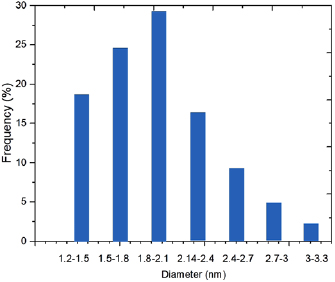
Figure 2. Histogram of cluster sizes.
Download figure:
Standard image High-resolution imageFigure 3 shows the UV–Vis spectrum of these Au NPs. As it is shown in figure 3, wide surface lasmon resonance band can be analyzed with the maximum around 550 nm. To verify the linkage of ligand on the surface of Au NPs, FTIR characterization was performed on the samples of ligand-capped AU NPs. Figure 4(a) clearly highlights the assembly of MUA on the surface of AU NPs. The peaks around 2919 and  referring to the asymmetric and symmetric stretching of –CH group. The characteristic peaks corresponding to acid group of O–H appear at
  . The peaks appear around at 1100, 1300 and
  indicate the Au NPs. Carbonyl group appears around
  . In different photoanodes of the cells,
  NPs were mixed with AU NPs (with and without ligand-capped). FTIR characterization was performed on these samples before and after calcination (figures 4(b)–(f)). The peaks around 2920 and
  are corresponding to the asymmetric and symmetric stretching of –CH group. The characteristic peaks equal to acid group of O–H appear at
  . The broad band around
  is likely because of the vibration of the Ti–O bonds in the
  lattice [21–23].
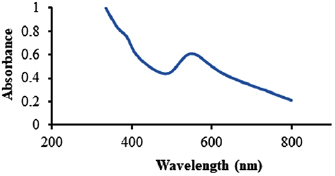
Figure 3. UV–Vis spectrum of Au nanoparticle.
Download figure:
Standard image High-resolution image
Figure 4. FTIR spectra of different samples: (a) MUA-ligand functionalized Au NPs; (b)  NPs; (c) and (d)
  nonpolar Au NPs and
  polar Au NPs paste before calcination; (e) and (f)
  nonpolar Au NPs and
  polar Au NPs paste after calcination.
Download figure:
Standard image High-resolution imageIn figure 4, the peak of the Ti–O bands in different samples of  and
and  can be examined before and after calcination and it has shifted in various samples, indicating the sorption of AU NPs on TiO2. Actually, the more is reduction of the shift, the better event is happened. The peak at
  indicates the presence
  . In the c-sample, which refers to a mixture of non-polar Au NPs loaded on
  before calcination, the peak appeared at
  . While d-sample, which is related to the mixture of polar Au NPs, loaded on
  before calcination, this peak is observed at
  , which suggests that the polar sample has had more blue shift and is more successful in adsorbing Au NPs. This is also true for (e) (and (f)) examples of
  /non-polar (and polar) Au NPs mixtures after calcination. The e-sample (non-polar gold NPs loaded on
  ) has a peak at
  and f-sample (polar Au NPs loaded on
  ) has a peak of
  , that f-sample indicating more blue shift. This suggests a better sorption of polar Au NPs on
  and can confirm that the COOH ligand has been able to better attract the Au NPs on
  . In addition, the yields of these samples are checked in DSSCs.
In this experiment, at first the Au NPs (with and without the COOH ligand) were added in  and mixed together for using in photoanode of the DSSC (A and B cells, respectively). The provided cells were characterized and electrochemical impedance spectroscopy was performed. Figure 5 indicates the typical
  curves of two cells (A & B cells). Table 1 summarizes this information, explaining the open circuit photovoltages, short-circuit photocurrents, fill factors, and efficiencies. From
  parameters, as reported in figure 5 and table 1, the two sensitized photoanodes (A and B photoanodes) showed different performance. The DSSC made of a gives the highest performance of 10.26% conversion efficiency. The capping of Au NPs with 11-mercaptoundecanoic acid ligands prevents the Au NPs from aggregation. Also it causes better link between Au and
  NPs (and dye molecules) and better sorption of Au onto
  , which can facilitate the transfer of electrons in the cell in the presence of suitable fermi level and ultimately leads to an increase in the photocurrent, photovoltage and efficiency of the DSSC [24]. To examine that the morphology of Au NPs has changed after functionalization or not, we tested the mixtures of
  and Au NPs via TEM. For these purpose different samples of COOH ligand-capped Au NPs and no ligand Au NPs were mixed with
  . These samples after calcinations are shown in figures 6 and (b) shows more agglomeration of Au NPs on
  . As mentioned, the reason for the use of Au NPs functionalized with carboxyl group is that the
  molecule is a polar metal oxide and can link with polar surfaces and acidic agents. Hence, the acid group can give a stronger bond through hydrogen bonding with
  and on the other hand, has the ability to bind with oxygen, according to the [25]. By modifying the surface of Au NPs and functionalizing them with a carboxyl group, you can obtain a homogeneous mixture of
  and Au NPs, while the paste containing
  and non-polar Au have not the proper uniformity, and Au particles accumulate in the corners of the paste. Stabilizing polymer and bonded ligands can play an important role in prevention of agglomeration NPs. Therefore, Au NPs without COOH ligand are not suitable for this purpose because of non-polarity. Also, carboxylic group can cause sorption of Au NPs on
  and dye.
Table 1. Summary of photovoltaic device performances.
| Cell |  |
 |
FF |  |
|---|---|---|---|---|
| A | 6.87 | 632.23 | 0.35 | 10.26 |
| B | 6.16 | 597.17 | 0.31 | 7.56 |
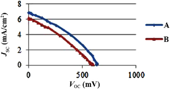
Figure 5.  characteristics of A and B plasmonic DSSCs.
Download figure:
Standard image High-resolution image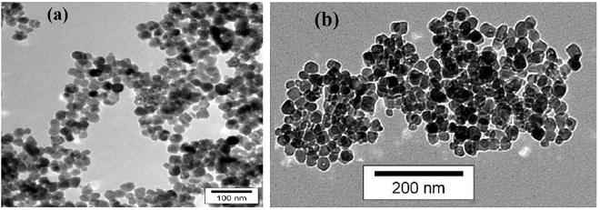
Figure 6. TEM images of  , with (a) and without the COOH ligand (b).
Download figure:
Standard image High-resolution imageBecause of having potential level of 5.1 eV, the fermi level of Au can be placed between conduction band of  and LUMO energy level of dye molecule that this helps the electron transfer in cell and accelerate electron moving and also decrease the probability of recombination of electrons with holes in dye. But the concentration of these particles is very important in this regard. Here the optimal concentration for mass ratio of Au/
 is used. To study the effect of the use of Au NPs, the cell with photoanode containing these NPs was compared with the base pigment cell. The results of the
  characteristics (figure 7) and the EIS measurement (figure 8) indicate the improvement of DSSC properties due to the use of polar Au NPs. DSSC characteristics with
  /dye photoanode stand for
  short circuit photocurrent density, 492.8 mV open circuit photovoltage, and a 7.4% average power conversion efficiency. While for the plasmonic DSSC contained Au NPs (
 /Au/dye photoanode), stand for
  short circuit photocurrent density, 527.8 mV open circuit photovoltage, and 11.7% average power conversion efficiency (figure 7).
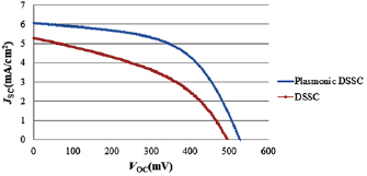
Figure 7.  characteristics of DSSC and plasmonic DSSC.
Download figure:
Standard image High-resolution image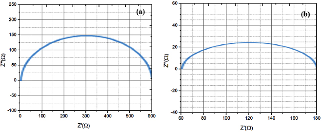
Figure 8. EIS measurement of the DSSC (a) and plasmonic DSSC (b).
Download figure:
Standard image High-resolution image
The results indicate a 14% increase in short circuit current density and 35 mV increase in open circuit voltage. The enhancement is caused by the plasmonic NPs which produce intensive local electromagnetic fields, and the enhancement couples the light from the far-field to the near field in active layer. In these intense local fields, the exaction generation rate in the dye molecule monolayer increases very much, thereby enhancing the photocurrent. Resistance to the best semi-circular fit of the EIS data of the two configurations in figure 8 are 96.2 Ω and 365 Ω for  /dye and
  /dye photoanodes respectively. The frequency range was between 0.01 to 100.000 Hz. This issue charges transfer resistances due to the traps in the photoanode, and recombination with the holes, and the recombination with the base dye states either.
Au NPs can increase the photocurrent and efficiency of the cell by reducing the photoanode resistance. Also, by estimation of the electron lifetime in a photoanode containing Au NPs, we see an increase in electron lifetime from 25 to 39 milliseconds. Electron transfer occurs quicker in a photoanode with a lower transfer charge resistance than other cells. On the other hand, the reason of increasing cell efficiency and less electron's recombination is caused by increasing the electron lifetime. The enhancement mechanism is related to the local electromagnetic response of the plasmonic NPs, which couples light strongly from the far field to the near field at the sorption dye molecule monolayer, thereby improving the local electron–hole pair (or exciton) generation rate effectively. Increase in VOC and Fill Factor can be related to decreased electron-hole recombination at  -dye-electrolyte interface. In addition to the typical plasma-induced increment of the light absorption for high photocurrent, the incorporation of Au NPs can result in negative shift of conduction band edge of
  and prevention of charge recombination, which make the photovoltage bigger and increases the power conversion efficiency [8, 26–29].
4. Conclusions
2 nm Au NPs which were loaded on  were synthesized by chemical reduction method and show solar energy conversion efficiency increase toward the unloaded
  NPs. To better adsorption of Au NPs on
  /dye and prevent aggregation and increase stability of Au NPs have utilized stabilizing COOH to functionalize the Au NPs and incorporated in the photoanode of DSSC. FTIR characterization confirmed the attachment of ligand on the surface of Au NPs. The combination of polar Au NPs with
  gives a homogeneous and suitable paste that uses it in photoanode of the cell to have a higher efficiency than the cells with photoanode containing non-polar Au NPs.
The results indicate an increase in the photocurrent and photovoltage and ultimately increase in the efficiency of the plasmonic DSSC. These cases are confirmed by measuring electrochemical impedance spectroscopy and its realized that with inlaid Au NPs in  photoanode resistance decreases and electron lifetime increases. The plasmonic enhancement results from the local electromagnetic fields and also reveals that direct charge transfer from Au to
  occurs. The small size of the Au NPs is advantageous because it does not reduce the effective area of
  in contact with the adsorbing dye molecules.