
Abstract
This report investigates systematically the effect of structural parameters on the left-handed behavior of a combined structure. The combined structure consists of a 'cut-wire pair', providing a negative magnetic permeability μ<0, and a 'continuous wire', yielding a negative electric permittivity ε<0. The left-handed metamaterials were designed, fabricated and measured in the microwave-frequency regime. It was found that the width of the continuous wire as well as the distance between the substructures play an important role in determining whether negative refractive properties (in other words, left-handed behavior) are obtained or not. Additionally, we studied the influence of the lattice constant on the electromagnetic response of the combined structure. The actual measurements are compared with numerical simulation values to show good coincidence. Finally, we designed and simulated an electromagnetic absorber made of metamaterials. It is expected that this work will allow us to optimize appropriate characteristic parameters even without avoiding trial and error fabrications.
Export citation and abstract BibTeX RIS

Content from this work may be used under the terms of the Creative Commons Attribution-NonCommercial-ShareAlike 3.0 licence. Any further distribution of this work must maintain attribution to the author(s) and the title of the work, journal citation and DOI.
1. Introduction
In recent years, materials with simultaneously negative permittivity and permeability (the so-called left-handed materials or LHMs) have become of special interest [1]. LHMs are understood to be artificially engineered materials that exhibit a number of highly unusual and often counterintuitive physical properties. They have therefore become a field of intense research activity, not only because of basic research but also their promising applications. Although metamaterial research activities only started quite recently, the results have already been covered in a number of monographs. Using resonant electromagnetic (EM) structures, a variety of metamaterials have been demonstrated in every technologically relevant spectral range, from the microwave [2] through the terahertz [3, 4] and near infrared regimes [5, 6], even up to visible frequencies [7, 8].
Many potential applications of metamaterials have been proposed and studied both theoretically and experimentally, such as superlenses [9], filters [10], antennas [11], electromagnetic cloaking [12, 13], biosensing [14] and, recently, perfect absorbers [15, 16]. In general, LHMs are artificial structures consisting of electric and magnetic components that have their own effective properties. To apply the uniform effective-medium theory in determining the effective permittivity and permeability of these structures, the size of the unit cell should be much smaller than the wavelength. Hence, nanofabrication technologies are crucial to obtain LHMs working at optical frequencies. Many interesting, but must-be-answered, questions on how to fabricate more isotropic LHMs and to push the operation frequency to optical wavelengths remain to be further explored. Therefore, the development of geometries and fabrication techniques for these materials is still an area of significant effort. The design and construction of magnetic and electric components play a central role in the EM response of LHMs.
In this research, we have used the cut-wire pair instead of the conventional split-ring resonator for constructing LHMs. The effect of the continuous wire width and the distance between them on the electromagnetic response of the combined structure was demonstrated. The influence of the lattice constant is also investigated. Finally, the electromagnetic absorber made of metamaterials is discussed. The effect of the structural parameters on the absorption properties of metamaterials is addressed. The metamaterials were designed, fabricated and measured in the microwave-frequency regime.
2. Experiment and simulation
Metamaterials were fabricated using the conventional printed circuit board (PCB) process with copper patterns (0.036 mm thick) on both sides of a dielectric PCB (0.4 mm thick) with a dielectric constant of 4.0. The length and width of the cut-wire pair are 5.5 and 1.0 mm, respectively. In order to obtain the LH behavior, the cut-wire pair structures were combined with the continuous wires. The unit cell of the combined structure is shown with its geometric parameters in figure 1(a). The transmission spectra were measured in free space using a Hewlett-Packard E8362B network analyzer connected to microwave standard-gain horn antennas.
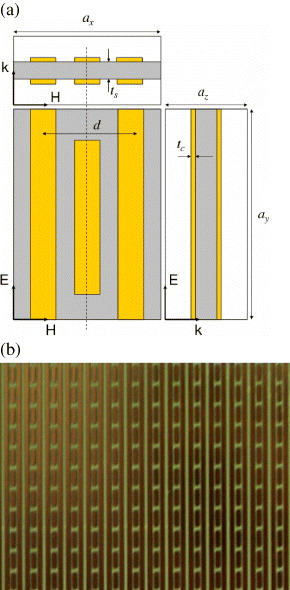
Figure 1 (a) Geometry of the unit cell of the combined structure is viewed from the E–H, E–k and k–H plane. (b) Photograph of a fabricated combined structure.
A computer simulation technology microwave studio was used for the numerical simulations. To obtain the effective parameters of the combined structure, we employed the retrieval procedure proposed by Chen et al [17]. For both simulation and experiment, the incident wave, k, is normal to the plane of the combined structure, while the electric field, E, is parallel to the continuous wire, as shown in figure 1.
3. Results and discussion
3.1. Negative refractive index of metamaterials
In this part, we present the results of the LH behavior, in other words, the negative refractive index of metamaterials based on the combined structure. The measured and calculated transmission spectra of the cut-wire pair and the combined structure are presented in figure 2, where the width of the cut-wire pair and continuous wire are kept at 1.0 mm. As can be seen, there exist two pass bands in the transmission spectra of the combined structure that are separated by a certain amount of frequency. A good agreement between measurements and numerical simulations was achieved. As expected, the first transmission peak of the combined structure at approximately 13.8 GHz coincides with the band gap of the cut-wire pair. This indicates that this pass band exhibits the LH behavior, but the other one at around 17 GHz is the right-handed (RH) behavior [18, 19]. The appearance of LH behavior can also be confirmed by using the extracted effective parameters of the combined structure, as presented in figures 2(c) and (d). Obviously, both the effective permeability and permittivity are negative around the first peak; consequently, the refractive index has a negative value (n < 0), in other words, exhibiting the LH behavior. However, the remaining peak exhibits the RH behavior because both permeability and permittivity are positive.

Figure 2 (a) Measured and (b) simulated transmission spectra of the cut-wire pair and the combined structure, where the width of the cut-wire and continuous wire are 1.0 mm and the lattice constant in the H, E and k directions is 6.5, 7.0 and 1.4 mm, respectively. (c and d) Real part of the permittivity and refractive index extracted from the simulation data. The inset is the effective permeability.
Besides the dependence of the structural parameters of the cut-wire pair on the LH behavior [19], we found that the electromagnetic response of the combined structure is considerably affected by the continuous wire. Figure 3 presents the transmission spectra of the combined structures with changing width of the continuous wire. For this study, the width of the cut-wire is kept at 1.0 mm while the width of the continuous wire is reduced from 1.0 to 0.5 mm.

Figure 3 (a) Measured and (b) simulated transmission spectra of the combined structure with different widths of continuous wires. (c and d) The permittivity and refractive index. The effective permeability is shown in the inset.
As can be seen, the transmission peak exhibiting the LH behavior is significantly enhanced with the decrease in width of the continuous wire; however, the peak position is almost unchanged (at 13.8 GHz). Together with this, it should be noted that the RH transmission peak seems to be shifted to a lower frequency as the width of the continuous wire is reduced. This makes the separation between these two peaks smaller. To verify this phenomenon, the effective permittivity, permeability and also refractive index of the combined structures are extracted from the scattering parameters, as presented in figures 3(c) and (d). As expected, the plasma frequency is moved to a lower frequency with decreasing width of the continuous wire, while the magnetic response is nearly unchanged. Therefore, this can explain why the RH peak is shifted to a lower frequency according to reducing the width of the continuous wire; consequently, the negative refractive index is degraded, as shown in figure 3(d). The enhancement of the LH behavior can be interpreted by the impedance matching of the LH medium with the vacuum background [20], where the wave interaction of the cut-wire pairs and continuous wires plays an important role for losses in the combined structure [21].
Another interesting result is shown in figure 4, where the LH behavior of the combined structure is also strongly affected by the distance d between the centers of the continuous wires. To study this phenomenon, the distance d was varied from 3.0 to 7.0 mm, and the lattice constant ax =2d, while ay =7.5 mm and az =1.4 mm. The effective permittivity, permeability and refractive index, obtained from the retrieval procedure, are shown to clarify this effect. As can be seen, the magnetic resonance band is nearly unchanged, but the plasma frequency is strongly shifted to a lower frequency with increasing distance between the centers of the continuous wires. This leads to the LH transmission band (in other words, the negative refractive index band) being reduced according to d. In case d reaches 7 mm or larger, the LH behavior is completely destroyed.
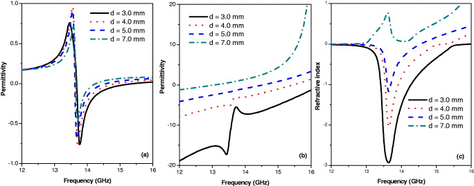
Figure 4 Extracted effective parameters of combined structure from the calculated scattering parameters: (a), (b) and (c) are the permittivity, permeability and refractive index, where the lattice constant in the E and k directions is ay =7.5 and az =1.4 mm, respectively, while the distance between the centers of the continuous wires d is varied from 3.0 to 7.0 mm, and the periodicity along the H-direction is kept to be ax =2d.
In this work, we also investigated the LH behavior dependence on the lattice constant. To study the influence of the lattice constant ay in the E-direction, the lattice constants along the H- and k-directions are kept at ax =6.5 mm and az =1.4 mm, respectively, while in the E-direction the lattice constant is varied from 6.5 to 7.5 mm. The effective parameters of these structures were retrieved from the calculated scattering parameters as given in figure 5. It is obvious that the electric response of the combined structure is significantly affected by ay . As ay is reduced, the plasma frequency of the combined structure is decreased. Even ay is decreased to 6.5 mm, the plasma frequency is still higher than the magnetic resonance frequency. This means that both the permeability and the permittivity of this structure are negative at the first peak (13.8 GHz). Therefore, the refractive index is still negative. If ay continues to be decreased, the plasma frequency is decreased accordingly to be lower than the magnetic frequency. At that time, the refractive index becomes positive; in other words, the LH behavior of these combined structures does not survive. This effect is due to the decrease in the electric resonance frequency of the cut-wire pair when the distance between the cut-wire pairs along the E-direction; in other words, ay is decreased. Consequently, this leads to a decreased plasma frequency of the combined structure.

Figure 5 Extracted effective parameters of combined structure: (a), (b) and (c) are the permittivity, permeability and refractive index, where the lattice constant in the H and k directions is ax =6.5 mm and az =1.4 mm, respectively, while the periodicity along the E-direction is varied from ay =6.5 to 7.5 mm.
To study the influence of the lattice constant ax on the EM response of the combined structure, the periodicity axis is varied from 6.0 to 7.0 mm, but the distance between the centers of continuous wires is kept at d=3.0 mm. At the same time, the periodicities in the (E, k) plane are ay =7.5 mm and az =1.4 mm, respectively. The extracted effective permittivity, permeability and refractive index are presented in figure 6. Interestingly, the negative refractive index is nearly unaffected by the lattice constant ax in the H-direction. This phenomenon is due to both the electric and the magnetic resonances of the cut-wire pair being almost unaffected by the lattice constant ax along the H-direction [22]. Therefore, when the cut-wire pairs are combined with the continuous wires, the plasma frequency of the combined structure will also not be affected by the ax .
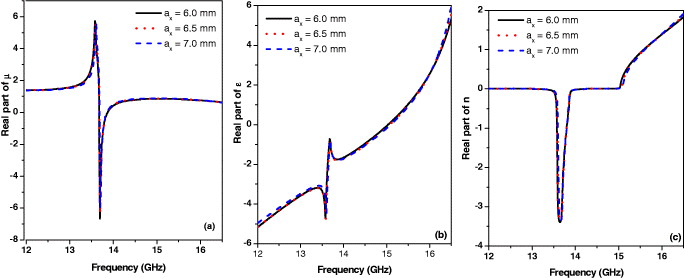
Figure 6 Extracted effective parameters of the combined structure: (a), (b) and (c) are the permittivity, permeability and refractive index, where the lattice constant in the E and k directions are ay =7.5 and az =1.4 mm, respectively, while the periodicity along the H-direction is varied form ax =6.0 to 7.0 mm.
For the lattice constant in the k-direction, we have studied in detail both theoretically and experimentally the effect of the lattice constants az on the EM response of the cut-wire pair medium and found that az provides subtle effects not only on the electric resonance but also on the magnetic resonance [22]. Therefore, when the cut-wire pairs are combined with the continuous wires, the magnetic and electric responses of the combined structure will also be significantly affected by az , which would consequently affect, in turn, the LH behavior of the combined structure. This effect might be similar to the case where the lattice constant ay is changing, as shown in figure 5. However, the cause of this phenomenon is quite different [23].
3.2. Electromagnetic absorber of metamaterials
Recently, the use of metamaterials as wave absorbers has attracted the interest of many researchers from the viewpoint of feasible metamaterial applications using current technology. In particular, MMs can be fashioned to create perfect absorbers by independently manipulating resonances in permittivity and permeability. Therefore, perfect absorption is becoming one of the most important properties for metamaterial absorbers. In this part, we present two different metamaterial structures for constructing the electromagnetic absorber. The first is shown in figure 7(a) with the unit cell consisted of two metallic parts that are separated by the dielectric layer. The first part is the electric ring resonator (ERR) providing the electric coupling and the other one supplies the magnetic coupling by combining the ERR and the wire. This structure is similar to the structure proposed by Landy et al [15].

Figure 7 (a) Geometry of the unit cell of the metamaterial absorber. (b) The simulated S-parameters and absorptance where g=0.54 mm, l=2.1 mm, ax =4.2 mm, ay =12 mm, w=0.6 mm, L=11.8 mm and t=0.2 mm.
The absorbance is calculated from the transmittance and the reflectance, and it is expressed by S21 and S11 parameters as A(ω )=1-|S11(ω )|2−|S21(ω )|2.
The simulated S-parameters and absorbance are shown in figure 7(b), where the structural parameters are defined as g=0.54 mm, l=2.1 mm, ax =4.2 mm, ay =12 mm, w=0.6 mm, L=11.8 mm and t=0.2 mm. It is found from figure 7(b) that the absorption reaches the maximum (A=96.4%) at 9.65 GHz, while the reflection is nearly zero.
Similar to the left-handed behavior, the electromagnetic absorption is also strongly affected by the structural parameters. One example is presented in figure 8(a), where the dielectric layer thickness is changed and other parameters are kept constant. Clearly, the electromagnetic absorption is increased with decreasing dielectric layer thickness from t=0.75 to 0.15 mm. When t is decreased until t=0.15 mm, the absorbance peak curve reaches the maximum values. However, if t is continually decreased, the absorption is decreased accordingly. The effect of the dielectric layer thickness can be explained due to changing the magnetic coupling of the structure according to the dielectric layer thickness [24].
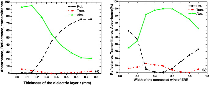
Figure 8 The reflectance, transmittance and absorptance depend on (a) the dielectric layer thickness t and (b) the width of connected wire of ERR.
Besides the dielectric layer thickness dependence, the absorption is also remarkably dependent on the structural parameters of the ERR. One of them is given in figure 8(b), where the width of the connected wire w of the ERR is changed. It is found from figure 8(b) that at w=0.45 mm the absorption has a maximum value and the reflection is at a minimum. This effect can be easily explained by changing the electric coupling of the ERR based on the LC equivalent circuit. The above results suggest that by independently manipulating resonances in permittivity and permeability along with matching them, we can easily create a high absorber metamaterial with minimum reflection.
Finally, we introduced another design of metamaterial absorber based on the cut-wire, as presented in figure 9(a). This structure comprises the single cut-wire metamaterial placed on a perfect electric conductor surface, as illustrated in figure 9(a). Compared with the structure shown in figure 7, the cut-wire metamaterials have a simpler structure. The periodic unit cell is composed of only a dielectric substrate and a single cut-wire. Due to this simplicity, cut-wire metamaterials are easy to fabricate and can be transformed into other types of metamaterials.
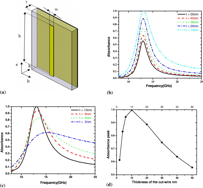
Figure 9 (a) The unit cell of the metamaterial absorber based on the cut-wire, where the length and width of the cut-wire are 6 and 1 mm, respectively, while the dielectric layer thickness is kept as 0.4 mm; (b), (c) and (d) show the dependence of the absorbance on the thickness of the cut-wire.
Interestingly, the absorbance is significantly affected by the thickness of the cut-wire, as presented in figures 9(a)–(c) where the thickness is varied from 2 to 50 nm. It is found in figure 9 that the positions of the maximum absorbance are fixed at around 13 GHz. In addition, it turns out that the absorbance peak curve reaches the maximum values with a cut-wire thickness of 10 nm. This absorbance peak dependence can also be explained by the LC equivalent circuit [25]. In addition, we have studied the effect of the cut-wire length as well as the dielectric layer thickness on the absorption. It was found that the position of the peak absorption is strongly dependent on the cut-wire length. This result suggests that we can design the broadband metamaterial absorber by using the structure with the unit cell consisting of different lengths of cut-wires.
4. Conclusions
We have studied the effect of the structural parameters on the left-handed behavior of a combined structure. It was found that the width of the continuous wire as well as the distance between the centers of the continuous wires strongly affect the left-handed behavior of the combined structure. In the extreme case, the left-handed behavior is completely eradicated. We also studied the influence of the lattice constant on the left-handed behavior of the combined structure. The results showed that the LH behavior is remarkably dependent on the lattice constant in the E- and k-directions. However, it remains unchanged according to the lattice constant in the H-direction. Finally, the electromagnetic absorber made of metamaterials was discussed. We presented two different metamaterial structures for constructing the electromagnetic absorber. Our results showed that, similar to the left-handed behavior, the absorption properties of metamaterials are also significantly affected by their structural parameters. The results suggest that by independently manipulating resonances in permittivity and permeability along with matching them, we can easily create a high absorber metamaterial with minimum reflection.
Acknowledgments
This work was supported by the Key Laboratory for Electronic Materials and Devices—Institute of Materials Science, Vietnam Academy of Science and Technology.