
Abstract
This study developed a bubble-free method for microfluidic devices and micropump applications by modifying the wetting characteristic of their chamber surfaces. Two methods of hydrophilic film formation were investigated, that is, microwave plasma surface modification and TiO2 thin film deposition. The evaluation results indicated that TiO2 thin film deposition showed better stability and it was therefore selected to improve the surface wettability and unify the spreading behavior. Different hydrophilic strip shape and strip numbers were investigated and the results indicated that the vertical design with trisection strip gives the best result and effectively discharges the bubbles of microfluidic devices. The results were then applied to a peristaltic micropump and very good results were obtained. That is, the micropump stability and robustness are enhanced significantly. Furthermore, in the pump operation frequency range (i.e. 75 ±10 Hz), bubbles are discharged effectively. The results show that when the micropump operated at frequencies lower than 100 Hz, air bubbles became insignificant; therefore, operation frequencies lower than 100 Hz are considered to be the micropump's stable performance range. From the results it was concluded that bubble formation is also responsible for the flow rate downhill effect.
Export citation and abstract BibTeX RIS

Content from this work may be used under the terms of the Creative Commons Attribution-NonCommercial-ShareAlike 3.0 licence. Any further distribution of this work must maintain attribution to the author(s) and the title of the work, journal citation and DOI.
1. Introduction
Our observations during previous experiments indicated that microfluidic devices and micropump chambers have internal bubbles while under operation. Another study [1] reported that this phenomenon is unavoidable and cannot be discharged due to the characteristics of microfluidic devices and micropumps. For microfluidic devices, bubbles reduce the reaction/mixing efficiency, and change the reaction/mixing properties. For micropumps, bubble formation leads to inconsistencies in net stroke volume and thus inconsistencies in flow rate. Therefore, reducing internal bubbles can enhance the stability, efficiency, and performance of microfluidic devices and diaphragm micropumps.
Experimental observation indicates that wetting or spreading inside the chamber is one of the most significant causes of bubble formation. The rate of wetting indicates how fast a liquid wets the surface and spreads over the surface. The wetting rate is affected by a number of factors such as the thermal conditions of the system, capillary forces, the viscosity of the liquid and the chemical reactions occurring at the interface [2].
The present study introduces a novel treatment method to conventional microfluidic systems and peristaltic micropump systems to optimize the wetting property inside their chambers which then unifies the spreading speed of the liquid over the chamber considered in the fluid flow direction. Surface modification techniques have attracted a lot of interest in studies of biomaterials, surface forces, spreading and for the control of interfacial interactions between materials and adsorbing biological molecules [3–5]. Hydrophilic surfaces can be produced either by a surface treatment that attaches individual polar groups, or by the deposition of a hydrophilic coating. Although using microwave plasma to modify surface properties is easier than using TiO 2 thin film deposition [5], the hydrophilic efficiency of the former decays with time while that of the latter does not. Accordingly, TiO 2 thin film deposition was chosen in this study to form a hydrophilic thin layer in the chamber. Various hydrophilic strip shapes and numbers of strips were investigated. The investigation and experiments were first conducted on a microfluidic system to determine the optimum design, which was then applied to a micropump system.
2. The basic concept of wetting and spreading dynamics
A review of wetting theory and spreading dynamics can be found in [2] and [6–9]. Some major conclusions that can be drawn from those studies are that a higher wetting surface has a smaller contact angle, which in turn generates a larger spreading area and faster spreading speed (i.e. higher spreading force). The spreading speed is initially high and then reduces according to the power law. However, the wetting of a solid by a liquid is a complex phenomenon that is affected by a large number of factors. Non-reactive wetting is generally affected by the material properties of the spreading liquid and substrate (i.e. wetting system), the roughness and heterogeneity of the surface, the physical properties of the spreading liquid and atmospheric conditions. The preceding discussion explains the internal bubble generation of microfluidic devices and micropumps. Our experimental observations indicate that water initially moves quickly at the chamber perimeter, causing bubbles (see section 4). The difference of spreading speeds across the chamber section is due to the wetting at the chamber perimeter being higher than that inside the chamber. Specifically, because the fluid–solid contact area at the perimeter is larger than that of the central part (i.e. the adding of a vertical chamber wall) therefore, the surface force, wettability and spreading speed at the perimeter is higher, which causes bubble formation. Consequently, the present study attempts to unify the wetting or spreading speed considered in the fluid flow direction to minimize bubble formation.
3. Experiment
3.1. TiO2 film stability evaluation
The stability of TiO 2 film under the effects of time and wear should be properly evaluated because it directly affects the stability of microfluidic devices and micropumps. Stability evaluation of hydrophilic film fabricated using two methods (i.e. microwave plasma surface modification and deposition) was conducted to determine which method offers higher stability for hydrophilic film.
3.1.1. Time dependent evaluation
The contact angle of DI (deionized) water resting on the untreated Poly(methyl methacrylate) (PMMA) surface was found to be 70° (details not shown). When the PMMA surface was treated with microwave plasma or TiO 2 deposition, the surface wetting changed, and therefore the contact angle changed. The contact angle varies with treatment duration (for microwave plasma) and TiO 2 solution concentration. In addition, the wetting and contact angle changes with time. The following experiments were conducted to investigate the time dependent characteristics of the treated surfaces.
3.1.2. Microwave plasma surface modification time dependent evaluation
Figure 1(a) shows the contact angle of DI water resting on a PMMA wafer treated with microwave plasma surface modification within 12 h of fabrication. The contact angle for a 1-min treatment is 54° and that for a 2-min treatment is 39°. The treatment duration clearly affects the wetting/contact angle. Longer treatment leads to a smaller contact angle. However, the contact angles are not stable but change with time. That is, after one week, both contact angles increased to 68°. Figure 1(b) shows the contact angle of DI water resting on a PMMA wafer treated with microwave plasma surface modification after one week. It is evident that the treated surface properties are not stable. In contrast, the PMMA wafer treated using the deposition method has a stable wetting property. The contact angle of DI water resting on a PMMA wafer treated with TiO 2 deposition observed after one week is almost unchanged and is about 11° (not shown). Consequently, the TiO 2 deposition method was selected for further evaluation. The stability of TiO 2 thin film was investigated under a fluid flow wear condition and with various solution concentrations.

Figure 1 Contact angle of DI water resting on a PMMA wafer treated with microwave plasma (a) within 12 h of fabrication and (b) after 1 week.
3.1.3. Wear resistance evaluation
The TiO 2 thin film produced in this study was exposed to fluid flow. Therefore, wear was considered. Firstly, wear changes the film wetting. Secondly, wear contaminates the working fluid and analysis sample. In this section, an experiment is conducted to evaluate the wear resistance of TiO 2 thin film. TiO 2 thin films fabricated using various solution concentrations were gradually exposed to water flow at a height of 30 cm for 30 s to observe wear resistance. The results show that samples fabricated from solutions with concentrations higher than 1:150 exhibited very low wear resistance. Figure 2(a) shows the experimental results of the sample with a 1:120 solution concentration ratio before and after the wear resistance test. The sample suffered significant wear. Figure 2(b) shows the experimental results for the sample with a 1:700 solution concentration ratio. The film was almost unaffected. Based on our observations, concentrations lower than 1:500 produce films with very high wear resistance. Although TiO 2 deposition is complex and the process is long, the wettability and stability are better than those obtained using plasma treatment. The deposition method was thus chosen to treat the micropump surface.

Figure 2 Experimental results for samples with solution concentration ratios of (a) 1:120 and (b) 1:700.
3.2. Bubble observation experiment
In this experiment, a TiO 2 solution concentration of 1:1100 was selected. The corresponding contact angle of TiO 2 thin film deposited on a PMMA wafer was around 11° (details not shown). The solution concentration was selected based on the preceding experimental results. The solution was deposited into the microfluidic system. The investigation was first conducted on a microfuilic system to obtain optimum parameters, which were then applied to a micropump system. Figure 3(a) shows the experimental setup for microfluidic system bubble observation. Two main devices were utilized in the experiment: a syringe-pump and a high-resolution video camera. The flow rate of the syringe-pump was set to10 μl min −1 to transfer the liquid (DI water). A video camera was used to observe the state of bubble behavior (i.e. formation, development, division and discharge).

Figure 3 Experiment setup of (a) microfluidic system bubble observation and (b) the micropump performance test and bubble observation.
After investigating and optimizing the hydrophilic thickness, shape, and number of strips, the results were applied to a micropump system. The pump performance test setup is shown in figure 3(b). Details of the micropump structure, experimental setup and equipment can be found in [10]. Bubble behavior (i.e. formation, development, division and discharge) was observed using a high-resolution video camera.
4. Results and discussion
After the surface properties were improved, the spreading dynamics of the fluid in the treated microfluidic system was better than that in the untreated one; the size of bubbles was also smaller and closer to the outlet, and therefore there was a higher chance of discharging the bubbles (see figures 4(a) and (b)). The spreading speed at the central line of the treated chamber was higher than that of the conventional chamber; therefore, when the spreading of the fluid met at two perimeters, the central line fluid spread further and closer to the outlet, which in turn resulted in smaller bubbles that were closer to the outlet. The quantity of bubbles decreased, but the bubbles could not be completely removed. Consequently, various shapes of TiO 2 thin film (i.e. ellipse, horizontal strip and vertical strip) were investigated. For the ellipse (figure 4(c)) and horizontal shapes (figure 4(d)), the fluid moved quicker through the hydrophilic segment; therefore, bubbles formed at the two perimeter parts (i.e. unfilled parts). For the vertical strip shape (figure 4(e)), the fluid moved uniformly; therefore, bubble formation was significantly reduced. Consequently, various vertical segmentation schemes (i.e. half, three sections and four sections) (see figure 5) were considered. In figure 5, for the half and four-section cases, the chamber did not completely fill with liquid, so bubbles appear at unfilled parts. When the segmentation was changed to three sections, the liquid gradually and uniformly moved toward the exit (i.e. filling section by section sequentially); therefore, most of the bubbles were eliminated. As a result, the three-section vertical-strip design is the optimum design to remove bubbles; it was thus applied to a micropump system.

Figure 4 Fluid spreading dynamics of (a) untreated, (b) uniformly covered, (c) ellipse, (d) horizontal and (e) vertical strips.
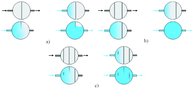
Figure 5 Spreading behavior and bubble formation mechanism of (a) half, (b) three-section and (c) four-section vertical strips.
The hydrophilic design was applied to a peristaltic micropump and the pump performance was then compared to that of a conventional micropump design. The results show that the maximum flow rates and back pressures of the untreated pump and the hydrophilic pump were 128.4 μl min −1 and 1134 mm H 2 O at 25 Hz 200 V pp and 57.6 μl min −1 and 395 mm H 2 O at 75 Hz 200 V pp , respectively (figure 6).
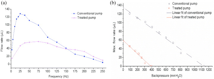
Figure 6 Performance of the micropumps. (a) Flow rate and (b) back pressure.
Figure 6(a) shows that the flow rate spectrum of the hydrophilic pump has a flatter peak, and therefore has a wider operation frequency range, which increases the stability of the micropump [11]. Therefore, discharging bubbles could increase the pump stability and accuracy. In addition, at high frequencies (i.e. higher than 150 Hz), the hydrophilic pump gives better performance compared to that of an untreated pump because the flow rate of the latter drops more significantly than that of the former. This is likely due to the reduction of bubble formation in the hydrophilic design. As discussed previously, bubble formation leads to inconsistencies in flow rate. Furthermore, bubble formation dissipates the actuation pressure inside the chambers and therefore reduces pumping efficiency. Consequently, it is concluded that the robustness of the hydrophilic pump is improved compared to a conventional pump and beside the initial effect [12], bubble formation at high frequencies is also responsible for the downhill characteristic of the pump's flow rate spectrum.
Video camera observation results of the micropump bubble formation indicate that the bubble state varies with the change of operation frequency. Specifically, bubbles do not appear clearly and the pump is very stable when the operation frequency is below 25 Hz. When the operation frequency is between 25 and 100 Hz, tiny bubbles appear and slowly move toward the exit. When the operation frequency is increased to between 100 and 200 Hz, the number of bubbles increases and the bubbles move faster. When the operation frequency is in the range of 200 to 250 Hz, the bubble speed further increases and the bubbles appear at the pump inlet. According to these results, at the pump operation frequency range (i.e. the frequencies corresponding to maximum flow rate and near the maximum flow rate with acceptable variation (i.e. 75±10 Hz)), the bubble issue is solved. Frequencies of below 100 Hz are considered the stable operation frequency range for the pump.
However, figure 6 shows that the performance (i.e. maximum flow rate and back pressure) of the hydrophilic pump is lower than that of the untreated pump. This is probably due to the height of the chamber being different in the hydrophilic micropump. Based on polarized light microscopy (PLM) observations of the cross section of the TiO 2 film, the film thickness was about 2 μm (not shown). Furthermore, because the contact angle changed from 71° to 11°, the adhesion force between the liquid and chamber wall became larger [2], which in turn resulted in a higher friction force. The change of chamber depth, surface profile, surface structure and surface friction force increased the system resistance; therefore, the efficiency of the micropump decreased.
5. Conclusion
A bubble-free method for microfluidic systems and micropump applications was developed. Two methods of hydrophilic film formation were investigated; TiO 2 thin film deposition exhibited better stability and was therefore selected for improving surface wettability. Various hydrophilic strip shapes and numbers of strips were investigated. The results indicate that the vertical design with a three-section strip most effectively discharges the bubbles in microfluidic devices. The optimum design was applied to a peristaltic micropump. The results indicate that the micropump stability and robustness were significantly increased. The number of bubbles was significantly reduced at the pump's operation frequency (i.e. 75 ± 10 Hz). The results show that frequencies of below 100 Hz are considered a stable operation frequency range for the pump. Although the proposed method produces lower pumping rates and backpressure, the results are considered important for microfluidic systems and micropumps.